
GS-5220-Series (V4) User Manual
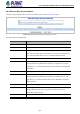

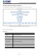
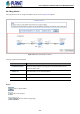
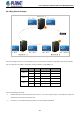
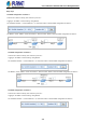
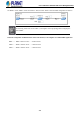
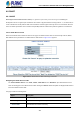
Table Of Contents
- 1. INTRODUCTION
- 2. INSTALLATION
- 3. SWITCH MANAGEMENT
- 4. WEB CONFIGURATION
- 4.1 Main Web Page
- 4.2 System
- 4.2.1 Management
- 4.2.1.1 System Information
- 4.2.1.2 IP Configuration
- 4.2.1.3 IP Status
- 4.2.1.4 Users Configuration
- 4.2.1.5 Privilege Levels
- 4.2.1.6 NTP Configuration
- 4.2.1.6.1 System Time Correction Manually
- 4.2.1.7 Time Configuration
- 4.2.1.8 UPnP
- 4.2.1.9 DHCP Relay
- 4.2.1.10 DHCP Relay Statistics
- 4.2.1.11 CPU Load
- 4.2.1.12 System Log
- 4.2.1.13 Detailed Log
- 4.2.1.14 Remote Syslog
- 4.2.1.15 SMTP Configuration
- 4.2.2 Simple Network Management Protocol
- 4.2.3 RMON
- 4.2.4 DHCP server
- 4.2.1 Management
- 4.3 Switching
- 4.3.1 Port Management
- 4.3.2 Link Aggregation
- 4.3.3 VLAN
- 4.3.3.1 VLAN Overview
- 4.3.3.2 IEEE 802.1Q VLAN
- 4.3.3.3 VLAN Port Configuration
- 4.3.3.4 VLAN Membership Status
- 4.3.3.5 VLAN Port Status
- 4.3.3.6 Private VLAN
- 4.3.3.7 Port Isolation
- 4.3.3.8 VLAN setting example:
- 4.3.3.8.1 Two Separate 802.1Q VLANs
- 4.3.3.8.2 VLAN Trunking between two 802.1Q aware switches
- 4.3.3.8.3 Port Isolate
- 4.3.3.9 MAC-based VLAN
- 4.3.3.10 Protocol-based VLAN
- 4.3.3.11 Protocol-based VLAN Membership
- 4.3.4 Spanning Tree Protocol
- 4.3.5 IGMP Snooping
- 4.3.6 MLD Snooping
- 4.3.7 MVR (Multicast VLAN Registration)
- 4.3.8 LLDP
- 4.3.9 MAC Address Table
- 4.3.10 Loop Protection
- 4.3.11 UDLD
- 4.3.12 GVRP
- 4.3.13 Link OAM
- 4.4 Routing
- 4.5 Quality of Service
- 4.6 Security
- 4.7 Power over Ethernet
- 4.8 Ring
- 4.9 ONVIF
- 4.10 Maintenance
- 5. SWITCH OPERATION
- 6. TROUBLESHOOTING
- APPENDIX A: Networking Connection
- APPENDIX B : GLOSSARY

User’s Manual of GS-5220 PoE Series Managed Switch
405
Instance Command:
Object Description
• Command
Administrative command. A port can be administratively configured to be in either
manual switch or forced switch state.
• Port
Port selection - Port0 or Port1 of the protection Group on which the command is
applied.
Instance State:
Object Description
• Protection State
ERPS state according to State Transition Tables in G.8032.
• Port 0
OK: State of East port is ok
SF: State of East port is Signal Fail
• Port 1
OK: State of West port is ok
SF: State of West port is Signal Fail
• Transmit APS
The transmitted APS according to State Transition Tables in G.8032.
• Port 0 Receive APS
The received APS on Port 0 according to State Transition Tables in G.8032.
• Port 1 Receive APS
The received APS on Port 1 according to State Transition Tables in G.8032.
• WTR Remaining
Remaining WTR timeout in milliseconds.
• RPL Un-blocked
APS is received on the working flow.
• No APS Received
RAPS PDU is not received from the other end.
• Port 0 Block Status
Block status for Port 0 (Both traffic and R-APS block status). R-APS channel is
never blocked on sub-rings without virtual channel.
• Port 1 Block Status
Block status for Port 1 (Both traffic and R-APS block status). R-APS channel is
never blocked on sub-rings without virtual channel.
• FOP Alarm
Failure of Protocol Defect(FOP) status. If FOP is detected, red LED glows; else
green LED glows.
Buttons
: Click to save changes.
Auto-refresh : Check this box to refresh the page automatically. Automatic refresh occurs every 6 seconds.
: Click to refresh the page immediately.
: Click to undo any changes made locally and revert to previously saved values.