
GS-5220-Series (V4) User Manual
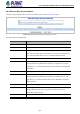

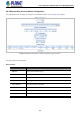
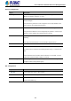
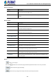
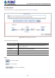
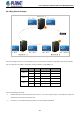
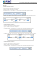
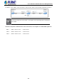
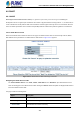
Table Of Contents
- 1. INTRODUCTION
- 2. INSTALLATION
- 3. SWITCH MANAGEMENT
- 4. WEB CONFIGURATION
- 4.1 Main Web Page
- 4.2 System
- 4.2.1 Management
- 4.2.1.1 System Information
- 4.2.1.2 IP Configuration
- 4.2.1.3 IP Status
- 4.2.1.4 Users Configuration
- 4.2.1.5 Privilege Levels
- 4.2.1.6 NTP Configuration
- 4.2.1.6.1 System Time Correction Manually
- 4.2.1.7 Time Configuration
- 4.2.1.8 UPnP
- 4.2.1.9 DHCP Relay
- 4.2.1.10 DHCP Relay Statistics
- 4.2.1.11 CPU Load
- 4.2.1.12 System Log
- 4.2.1.13 Detailed Log
- 4.2.1.14 Remote Syslog
- 4.2.1.15 SMTP Configuration
- 4.2.2 Simple Network Management Protocol
- 4.2.3 RMON
- 4.2.4 DHCP server
- 4.2.1 Management
- 4.3 Switching
- 4.3.1 Port Management
- 4.3.2 Link Aggregation
- 4.3.3 VLAN
- 4.3.3.1 VLAN Overview
- 4.3.3.2 IEEE 802.1Q VLAN
- 4.3.3.3 VLAN Port Configuration
- 4.3.3.4 VLAN Membership Status
- 4.3.3.5 VLAN Port Status
- 4.3.3.6 Private VLAN
- 4.3.3.7 Port Isolation
- 4.3.3.8 VLAN setting example:
- 4.3.3.8.1 Two Separate 802.1Q VLANs
- 4.3.3.8.2 VLAN Trunking between two 802.1Q aware switches
- 4.3.3.8.3 Port Isolate
- 4.3.3.9 MAC-based VLAN
- 4.3.3.10 Protocol-based VLAN
- 4.3.3.11 Protocol-based VLAN Membership
- 4.3.4 Spanning Tree Protocol
- 4.3.5 IGMP Snooping
- 4.3.6 MLD Snooping
- 4.3.7 MVR (Multicast VLAN Registration)
- 4.3.8 LLDP
- 4.3.9 MAC Address Table
- 4.3.10 Loop Protection
- 4.3.11 UDLD
- 4.3.12 GVRP
- 4.3.13 Link OAM
- 4.4 Routing
- 4.5 Quality of Service
- 4.6 Security
- 4.7 Power over Ethernet
- 4.8 Ring
- 4.9 ONVIF
- 4.10 Maintenance
- 5. SWITCH OPERATION
- 6. TROUBLESHOOTING
- APPENDIX A: Networking Connection
- APPENDIX B : GLOSSARY

User’s Manual of GS-5220 PoE Series Managed Switch
401
4.8.3 Ethernet Ring Protocol Switch
The Ethernet Ring Protection Switch instances are configured here; screen in Figure 4-8-3 appears.
Figure 4-8-3: Ethernet Ring Protocol Switch page screenshot
The page includes the following fields:
Object Description
• Delete
This box is used to mark an ERPS for deletion in next Save operation.
• Port 0
This will create a Port 0 of the switch in the ring.
• Port 1
This will create "Port 1" of the switch in the Ring. As interconnected sub-ring will
have only one ring port, "Port 1" is configured as "0" for interconnected sub-ring.
"0" in this field indicates that no "Port 1" is associated with this instance
• Port 0 SF MEP
The Port 0 Signal Fail reporting MEP.
• Port 1 SF MEP
The Port 1 Signal Fail reporting MEP. As only one SF MEP is associated with
interconnected sub-ring without virtual channel, it is configured as "0" for such
ring instances. "0" in this field indicates that no Port 1 SF MEP is associated with
this instance.
• Port 0 APS MEP
The Port 0 APS PDU handling MEP.
• Port 1 APS MEP
The Port 1 APS PDU handling MEP. As only one APS MEP is associated with
interconnected sub-ring without virtual channel, it is configured as "0" for such
ring instances. "0" in this field indicates that no Port 1 APS MEP is associated
with this instance.
• Ring Type
Type of Protecting ring. It can be either major ring or sub-ring.
• Major Ring ID
Major ring group ID for the interconnected sub-ring. It is used to send topology
change updates on major ring. If ring is major, this value is same as the
protection group ID of this ring.
• Alarm
There is an active alarm on the ERPS.