
GS-5220-Series (V4) User Manual
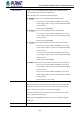


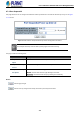

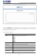
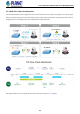
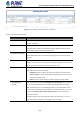
Table Of Contents
- 1. INTRODUCTION
- 2. INSTALLATION
- 3. SWITCH MANAGEMENT
- 4. WEB CONFIGURATION
- 4.1 Main Web Page
- 4.2 System
- 4.2.1 Management
- 4.2.1.1 System Information
- 4.2.1.2 IP Configuration
- 4.2.1.3 IP Status
- 4.2.1.4 Users Configuration
- 4.2.1.5 Privilege Levels
- 4.2.1.6 NTP Configuration
- 4.2.1.6.1 System Time Correction Manually
- 4.2.1.7 Time Configuration
- 4.2.1.8 UPnP
- 4.2.1.9 DHCP Relay
- 4.2.1.10 DHCP Relay Statistics
- 4.2.1.11 CPU Load
- 4.2.1.12 System Log
- 4.2.1.13 Detailed Log
- 4.2.1.14 Remote Syslog
- 4.2.1.15 SMTP Configuration
- 4.2.2 Simple Network Management Protocol
- 4.2.3 RMON
- 4.2.4 DHCP server
- 4.2.1 Management
- 4.3 Switching
- 4.3.1 Port Management
- 4.3.2 Link Aggregation
- 4.3.3 VLAN
- 4.3.3.1 VLAN Overview
- 4.3.3.2 IEEE 802.1Q VLAN
- 4.3.3.3 VLAN Port Configuration
- 4.3.3.4 VLAN Membership Status
- 4.3.3.5 VLAN Port Status
- 4.3.3.6 Private VLAN
- 4.3.3.7 Port Isolation
- 4.3.3.8 VLAN setting example:
- 4.3.3.8.1 Two Separate 802.1Q VLANs
- 4.3.3.8.2 VLAN Trunking between two 802.1Q aware switches
- 4.3.3.8.3 Port Isolate
- 4.3.3.9 MAC-based VLAN
- 4.3.3.10 Protocol-based VLAN
- 4.3.3.11 Protocol-based VLAN Membership
- 4.3.4 Spanning Tree Protocol
- 4.3.5 IGMP Snooping
- 4.3.6 MLD Snooping
- 4.3.7 MVR (Multicast VLAN Registration)
- 4.3.8 LLDP
- 4.3.9 MAC Address Table
- 4.3.10 Loop Protection
- 4.3.11 UDLD
- 4.3.12 GVRP
- 4.3.13 Link OAM
- 4.4 Routing
- 4.5 Quality of Service
- 4.6 Security
- 4.7 Power over Ethernet
- 4.8 Ring
- 4.9 ONVIF
- 4.10 Maintenance
- 5. SWITCH OPERATION
- 6. TROUBLESHOOTING
- APPENDIX A: Networking Connection
- APPENDIX B : GLOSSARY

User’s Manual of GS-5220 PoE Series Managed Switch
384
• System Power Budget
Displays the maximum PoE power budget.
• Operation Mode
Displays the current PoE operation mode.
• Current Budget
Displays the current maximum PoE budget.
• Current Ports in Use
Displays the current PoE ports in use.
• Class 1 ~ 8 ports
Displays the current ports of PoE class 1 ~ 8.
• Power Consumption
Displays the current power consumption (total watts and percentage)
• PoE Temperature
Displays the current operating temperature of the first PoE chip unit.
• Current Power
Consumption
Shows the total watts usage of Managed PoE Switch.
• Total Power Reserved
Shows how much the total power is reserved for all PDs.
• Temperature
Displays the current operating temperature of the PoE chip unit.
• Local Port
This is the logical port number for this row.
• PD Class
Displays the class of the PD attached to the port, as established by the classification
process. Class 0 is the default for PDs. The PD is powered based on PoE Class
level if system is working in Classification mode. A PD will return Class to 0 to 4 in
accordance with the maximum power draw as specified by Table 4-8-1-1.
• Power Used [W]
The Power Used shows how much power the PD currently is using.
• Current Used [mA]
The Power Used shows how much current the PD currently is using.
• Priority
The Priority shows the port's priority configured by the user.
• Port Status
The Port Status shows the port's status.
• Power Inline Mode
Displays per PoE port operating in mid-span, end-span or UPoE mode.
• Total
Shows the total power and current usage of all PDs.
Buttons
Auto-refresh : Check this box to enable an automatic refresh of the page at regular intervals.
: Click to refresh the page immediately.