
GS-5220-Series (V4) User Manual


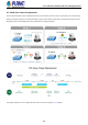
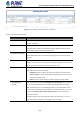
Table Of Contents
- 1. INTRODUCTION
- 2. INSTALLATION
- 3. SWITCH MANAGEMENT
- 4. WEB CONFIGURATION
- 4.1 Main Web Page
- 4.2 System
- 4.2.1 Management
- 4.2.1.1 System Information
- 4.2.1.2 IP Configuration
- 4.2.1.3 IP Status
- 4.2.1.4 Users Configuration
- 4.2.1.5 Privilege Levels
- 4.2.1.6 NTP Configuration
- 4.2.1.6.1 System Time Correction Manually
- 4.2.1.7 Time Configuration
- 4.2.1.8 UPnP
- 4.2.1.9 DHCP Relay
- 4.2.1.10 DHCP Relay Statistics
- 4.2.1.11 CPU Load
- 4.2.1.12 System Log
- 4.2.1.13 Detailed Log
- 4.2.1.14 Remote Syslog
- 4.2.1.15 SMTP Configuration
- 4.2.2 Simple Network Management Protocol
- 4.2.3 RMON
- 4.2.4 DHCP server
- 4.2.1 Management
- 4.3 Switching
- 4.3.1 Port Management
- 4.3.2 Link Aggregation
- 4.3.3 VLAN
- 4.3.3.1 VLAN Overview
- 4.3.3.2 IEEE 802.1Q VLAN
- 4.3.3.3 VLAN Port Configuration
- 4.3.3.4 VLAN Membership Status
- 4.3.3.5 VLAN Port Status
- 4.3.3.6 Private VLAN
- 4.3.3.7 Port Isolation
- 4.3.3.8 VLAN setting example:
- 4.3.3.8.1 Two Separate 802.1Q VLANs
- 4.3.3.8.2 VLAN Trunking between two 802.1Q aware switches
- 4.3.3.8.3 Port Isolate
- 4.3.3.9 MAC-based VLAN
- 4.3.3.10 Protocol-based VLAN
- 4.3.3.11 Protocol-based VLAN Membership
- 4.3.4 Spanning Tree Protocol
- 4.3.5 IGMP Snooping
- 4.3.6 MLD Snooping
- 4.3.7 MVR (Multicast VLAN Registration)
- 4.3.8 LLDP
- 4.3.9 MAC Address Table
- 4.3.10 Loop Protection
- 4.3.11 UDLD
- 4.3.12 GVRP
- 4.3.13 Link OAM
- 4.4 Routing
- 4.5 Quality of Service
- 4.6 Security
- 4.7 Power over Ethernet
- 4.8 Ring
- 4.9 ONVIF
- 4.10 Maintenance
- 5. SWITCH OPERATION
- 6. TROUBLESHOOTING
- APPENDIX A: Networking Connection
- APPENDIX B : GLOSSARY

User’s Manual of GS-5220 PoE Series Managed Switch
381
• PoE Inline Mode
It allows user to select IEEE802.3at/802.3bt/Ultra PoE compatibility mode to
meet all PoE PD types for various PoE applications.
Setting the Right Power Inline Mode for Each Application:
Midspan: Set inline mode to IEEE 802.3at PoE+ Mid-span PSE.
Pins 4-5 (pair #1 in both T568A and T568B) form one side of
the DC supply and pins 7-8 (pair #4 in both T568A and T568B)
provide the return.
Maximum power is 36.0 watts.
Endspan: Set inline mode to IEEE 802.3at PoE+ End-span PSE.
Pins 1-2 (pair #2 in both T568A and T568B) form one side of
the DC supply and pins 3-6 (pair #3 in both T568A and T568B)
provide the return.
Maximum power is 36.0 watts.
802.3bt: Set inline mode to IEEE 802.3bt PoE++ Type-4 or Type-3 PSE.
Pins 1-2 (pair #2 in both T568A and T568B) form one side of
the DC supply and pins 3-6 (pair #3 in both T568A and T568B)
provide the return.
Pins 4-5 (pair #1 in both T568A and T568B) form one side of
the DC supply and pins 7-8 (pair #4 in both T568A and T568B)
provide the return.
Maximum power is 90~60 watts.
UPOE: Set inline mode to PoH (Power over HD-BASE-T) 4-pair PoE+ PSE
Pins 1-2 (pair #2 in both T568A and T568B) form one side of
the DC supply and pins 3-6 (pair #3 in both T568A and T568B)
provide the return.
Pins 4-5 (pair #1 in both T568A and T568B) form one side of
the DC supply and pins 7-8 (pair #4 in both T568A and T568B)
provide the return
Maximum power is 72-60.0 watts
• Force Power
It allows user to enable force power function in a specified PoE Inline mode.
Once the force power is enabled, the PoE port will ignore the PoE classification
behaviors and directly deliver power over UTP cable no matter what Ethernet
device is attached, or even there is no Ethernet cable plugged.
Please be careful when using force power function and make sure the remote
device is PoE powered device (PD).
Maximum power is 60 watts when PoE Inline mode is configured to 8023bt or
UPOE mode.
• PoE Extension
For user to enable or disable per port PoE Extension function.