
GS-5220-Series (V4) User Manual
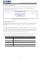

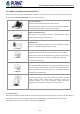
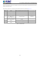
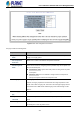

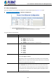
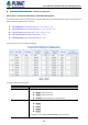
Table Of Contents
- 1. INTRODUCTION
- 2. INSTALLATION
- 3. SWITCH MANAGEMENT
- 4. WEB CONFIGURATION
- 4.1 Main Web Page
- 4.2 System
- 4.2.1 Management
- 4.2.1.1 System Information
- 4.2.1.2 IP Configuration
- 4.2.1.3 IP Status
- 4.2.1.4 Users Configuration
- 4.2.1.5 Privilege Levels
- 4.2.1.6 NTP Configuration
- 4.2.1.6.1 System Time Correction Manually
- 4.2.1.7 Time Configuration
- 4.2.1.8 UPnP
- 4.2.1.9 DHCP Relay
- 4.2.1.10 DHCP Relay Statistics
- 4.2.1.11 CPU Load
- 4.2.1.12 System Log
- 4.2.1.13 Detailed Log
- 4.2.1.14 Remote Syslog
- 4.2.1.15 SMTP Configuration
- 4.2.2 Simple Network Management Protocol
- 4.2.3 RMON
- 4.2.4 DHCP server
- 4.2.1 Management
- 4.3 Switching
- 4.3.1 Port Management
- 4.3.2 Link Aggregation
- 4.3.3 VLAN
- 4.3.3.1 VLAN Overview
- 4.3.3.2 IEEE 802.1Q VLAN
- 4.3.3.3 VLAN Port Configuration
- 4.3.3.4 VLAN Membership Status
- 4.3.3.5 VLAN Port Status
- 4.3.3.6 Private VLAN
- 4.3.3.7 Port Isolation
- 4.3.3.8 VLAN setting example:
- 4.3.3.8.1 Two Separate 802.1Q VLANs
- 4.3.3.8.2 VLAN Trunking between two 802.1Q aware switches
- 4.3.3.8.3 Port Isolate
- 4.3.3.9 MAC-based VLAN
- 4.3.3.10 Protocol-based VLAN
- 4.3.3.11 Protocol-based VLAN Membership
- 4.3.4 Spanning Tree Protocol
- 4.3.5 IGMP Snooping
- 4.3.6 MLD Snooping
- 4.3.7 MVR (Multicast VLAN Registration)
- 4.3.8 LLDP
- 4.3.9 MAC Address Table
- 4.3.10 Loop Protection
- 4.3.11 UDLD
- 4.3.12 GVRP
- 4.3.13 Link OAM
- 4.4 Routing
- 4.5 Quality of Service
- 4.6 Security
- 4.7 Power over Ethernet
- 4.8 Ring
- 4.9 ONVIF
- 4.10 Maintenance
- 5. SWITCH OPERATION
- 6. TROUBLESHOOTING
- APPENDIX A: Networking Connection
- APPENDIX B : GLOSSARY

User’s Manual of GS-5220 PoE Series Managed Switch
380
GS-5220 802.3bt PoE++ Switch – PoE Port Configuration
802.3bt PoE++ and Advanced PoE Power Output Mode Management
To meet the demand of various powered devices consuming stable PoE power, the GS-5220 PoE++ Switch series provides five
different PoE power output modes for selection.
95W UPOE/PoH Power Output Mode (Pins 1, 2, 3, 6 + Pins 4, 5, 7, 8)
90W 802.3bt PoE++ Power Output Mode (Pins 1, 2, 3, 6 + Pins 4, 5, 7, 8)
60W Force Power Output Mode (Pins 1, 2, 3, 6 + Pins 4, 5, 7, 8)
30W End-span PoE Power Output Mode (Pins 1, 2, 3, 6)
30W Mid-span PoE Power Output Mode (Pins 4, 5, 7, 8)
This page allows user to set up PoE port attributes.
The page includes the following fields:
Object Description
• PoE Mode
There are three modes for PoE mode.
Enable: enable PoE function..
Disable: disable PoE function.
Schedule: enable PoE function in schedule mode.
• Schedule
Indicates the schedule profile mode. Possible profiles are:
Profile1
Profile2
Profile3
Profile4
To enable this feature, NTP and PoE schedule must be enable first.