
GS-5220-Series (V4) User Manual
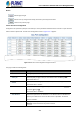
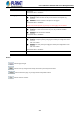
Table Of Contents
- 1. INTRODUCTION
- 2. INSTALLATION
- 3. SWITCH MANAGEMENT
- 4. WEB CONFIGURATION
- 4.1 Main Web Page
- 4.2 System
- 4.2.1 Management
- 4.2.1.1 System Information
- 4.2.1.2 IP Configuration
- 4.2.1.3 IP Status
- 4.2.1.4 Users Configuration
- 4.2.1.5 Privilege Levels
- 4.2.1.6 NTP Configuration
- 4.2.1.6.1 System Time Correction Manually
- 4.2.1.7 Time Configuration
- 4.2.1.8 UPnP
- 4.2.1.9 DHCP Relay
- 4.2.1.10 DHCP Relay Statistics
- 4.2.1.11 CPU Load
- 4.2.1.12 System Log
- 4.2.1.13 Detailed Log
- 4.2.1.14 Remote Syslog
- 4.2.1.15 SMTP Configuration
- 4.2.2 Simple Network Management Protocol
- 4.2.3 RMON
- 4.2.4 DHCP server
- 4.2.1 Management
- 4.3 Switching
- 4.3.1 Port Management
- 4.3.2 Link Aggregation
- 4.3.3 VLAN
- 4.3.3.1 VLAN Overview
- 4.3.3.2 IEEE 802.1Q VLAN
- 4.3.3.3 VLAN Port Configuration
- 4.3.3.4 VLAN Membership Status
- 4.3.3.5 VLAN Port Status
- 4.3.3.6 Private VLAN
- 4.3.3.7 Port Isolation
- 4.3.3.8 VLAN setting example:
- 4.3.3.8.1 Two Separate 802.1Q VLANs
- 4.3.3.8.2 VLAN Trunking between two 802.1Q aware switches
- 4.3.3.8.3 Port Isolate
- 4.3.3.9 MAC-based VLAN
- 4.3.3.10 Protocol-based VLAN
- 4.3.3.11 Protocol-based VLAN Membership
- 4.3.4 Spanning Tree Protocol
- 4.3.5 IGMP Snooping
- 4.3.6 MLD Snooping
- 4.3.7 MVR (Multicast VLAN Registration)
- 4.3.8 LLDP
- 4.3.9 MAC Address Table
- 4.3.10 Loop Protection
- 4.3.11 UDLD
- 4.3.12 GVRP
- 4.3.13 Link OAM
- 4.4 Routing
- 4.5 Quality of Service
- 4.6 Security
- 4.7 Power over Ethernet
- 4.8 Ring
- 4.9 ONVIF
- 4.10 Maintenance
- 5. SWITCH OPERATION
- 6. TROUBLESHOOTING
- APPENDIX A: Networking Connection
- APPENDIX B : GLOSSARY

User’s Manual of GS-5220 PoE Series Managed Switch
355
■ Any: No destination IP filter is specified. (Destination IP filter is
"don't-care".)
■ Host: Destination IP filter is set to Host. Specify the destination IP address
in the DIP Address field that appears.
■ Network: Destination IP filter is set to Network. Specify the destination IP
address and destination IP mask in the DIP Address and DIP Mask fields
that appear.
• DIP Address
When "Host" or "Network" is selected for the destination IP filter, you can enter a
specific DIP address in dotted decimal notation.
• DIP Mask
When "Network" is selected for the destination IP filter, you can enter a specific
DIP mask in dotted decimal notation.
IPv6 Parameters
Object Description
• Next Header Filter
Specify the IPv6 next header filter for this ACE.
■ Any: No IPv6 next header filter is specified ("don't-care").
■ Specific: If you want to filter a specific IPv6 next header filter with this
ACE, choose this value. A field for entering an IPv6 next header filter
appears.
■ ICMP: Select ICMP to filter IPv6 ICMP protocol frames. Extra fields for
defining ICMP parameters will appear. These fields are explained later in
this help file.
■ UDP: Select UDP to filter IPv6 UDP protocol frames. Extra fields for
defining UDP parameters will appear. These fields are explained later in
this help file.
■ TCP: Select TCP to filter IPv6 TCP protocol frames. Extra fields for defining
TCP parameters will appear. These fields are explained later in this help
file.
• Next Header Value
When "Specific" is selected for the IPv6 next header value, you can enter a
specific value. The allowed range is 0 to 255. A frame that hits this ACE matches
this IPv6 protocol value.
• SIP Filter
Specify the source IPv6 filter for this ACE.
■ Any: No source IPv6 filter is specified. (Source IPv6 filter is "don't-care".)
■ Specific: Source IPv6 filter is set to Network. Specify the source IPv6
address and source IPv6 mask in the SIP Address fields that appear.
• SIP Address
When "Specific" is selected for the source IPv6 filter, you can enter a specific
SIPv6 address. The field only supported last 32 bits for IPv6 address.
• SIP BitMask
When "Specific" is selected for the source IPv6 filter, you can enter a specific
SIPv6 mask. The field only supported last 32 bits for IPv6 address. Notice the