
GS-5220-Series (V4) User Manual
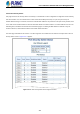

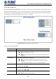
Table Of Contents
- 1. INTRODUCTION
- 2. INSTALLATION
- 3. SWITCH MANAGEMENT
- 4. WEB CONFIGURATION
- 4.1 Main Web Page
- 4.2 System
- 4.2.1 Management
- 4.2.1.1 System Information
- 4.2.1.2 IP Configuration
- 4.2.1.3 IP Status
- 4.2.1.4 Users Configuration
- 4.2.1.5 Privilege Levels
- 4.2.1.6 NTP Configuration
- 4.2.1.6.1 System Time Correction Manually
- 4.2.1.7 Time Configuration
- 4.2.1.8 UPnP
- 4.2.1.9 DHCP Relay
- 4.2.1.10 DHCP Relay Statistics
- 4.2.1.11 CPU Load
- 4.2.1.12 System Log
- 4.2.1.13 Detailed Log
- 4.2.1.14 Remote Syslog
- 4.2.1.15 SMTP Configuration
- 4.2.2 Simple Network Management Protocol
- 4.2.3 RMON
- 4.2.4 DHCP server
- 4.2.1 Management
- 4.3 Switching
- 4.3.1 Port Management
- 4.3.2 Link Aggregation
- 4.3.3 VLAN
- 4.3.3.1 VLAN Overview
- 4.3.3.2 IEEE 802.1Q VLAN
- 4.3.3.3 VLAN Port Configuration
- 4.3.3.4 VLAN Membership Status
- 4.3.3.5 VLAN Port Status
- 4.3.3.6 Private VLAN
- 4.3.3.7 Port Isolation
- 4.3.3.8 VLAN setting example:
- 4.3.3.8.1 Two Separate 802.1Q VLANs
- 4.3.3.8.2 VLAN Trunking between two 802.1Q aware switches
- 4.3.3.8.3 Port Isolate
- 4.3.3.9 MAC-based VLAN
- 4.3.3.10 Protocol-based VLAN
- 4.3.3.11 Protocol-based VLAN Membership
- 4.3.4 Spanning Tree Protocol
- 4.3.5 IGMP Snooping
- 4.3.6 MLD Snooping
- 4.3.7 MVR (Multicast VLAN Registration)
- 4.3.8 LLDP
- 4.3.9 MAC Address Table
- 4.3.10 Loop Protection
- 4.3.11 UDLD
- 4.3.12 GVRP
- 4.3.13 Link OAM
- 4.4 Routing
- 4.5 Quality of Service
- 4.6 Security
- 4.7 Power over Ethernet
- 4.8 Ring
- 4.9 ONVIF
- 4.10 Maintenance
- 5. SWITCH OPERATION
- 6. TROUBLESHOOTING
- APPENDIX A: Networking Connection
- APPENDIX B : GLOSSARY

User’s Manual of GS-5220 PoE Series Managed Switch
342
The page includes the following fields:
User Module Legend
The legend shows all user modules that may request Port Security services.
Object Description
• User Module Name
The full name of a module that may request Port Security services.
• Abbr
A one-letter abbreviation of the user module. This is used in the Users column in
the port status table.
Port Status
The table has one row for each port on the selected switch in the switch and a number of columns, which are:
Object Description
• Clear
Click to remove all MAC addresses on all VLANs on this port. The button is only
clickable if number of secured MAC addresses is non-zero.
• Port
The port number for which the status applies. Click the port number to see the
status for this particular port.
• Users
Each of the user modules has a column that shows whether that module has
enabled Port Security or not. A '-' means that the corresponding user module is
not enabled, whereas a letter indicates that the user module abbreviated by that
letter has enabled port security.
• Violation Mode
Shows the configured Violation Mode of the port. It can take one of four values:
Disabled: Port Security is not administratively enabled on this port.
Protect: Port Security is administratively enabled in Protect mode.
Restrict: Port Security is administratively enabled in Restrict mode.
Shutdown: Port Security is administratively enabled in Shutdown mode.
• State
Shows the current state of the port. It can take one of four values:
Disabled: No user modules are currently using the Port Security service.
Ready: The Port Security service is in use by at least one user module, and
is awaiting frames from unknown MAC addresses to arrive.
Limit Reached: The Port Security service is enabled by at least the Limit
Control user module, and that module has indicated that the limit is reached
and no more MAC addresses should be taken in.
Shutdown: The Port Security service is enabled by at least the Limit Control
user module, and that module has indicated that the limit is exceeded. No
MAC addresses can be learned on the port until it is administratively
re-opened on the Limit Control configuration web page.