
GS-5220-Series (V4) User Manual
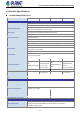
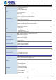
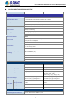
Table Of Contents
- 1. INTRODUCTION
- 2. INSTALLATION
- 3. SWITCH MANAGEMENT
- 4. WEB CONFIGURATION
- 4.1 Main Web Page
- 4.2 System
- 4.2.1 Management
- 4.2.1.1 System Information
- 4.2.1.2 IP Configuration
- 4.2.1.3 IP Status
- 4.2.1.4 Users Configuration
- 4.2.1.5 Privilege Levels
- 4.2.1.6 NTP Configuration
- 4.2.1.6.1 System Time Correction Manually
- 4.2.1.7 Time Configuration
- 4.2.1.8 UPnP
- 4.2.1.9 DHCP Relay
- 4.2.1.10 DHCP Relay Statistics
- 4.2.1.11 CPU Load
- 4.2.1.12 System Log
- 4.2.1.13 Detailed Log
- 4.2.1.14 Remote Syslog
- 4.2.1.15 SMTP Configuration
- 4.2.2 Simple Network Management Protocol
- 4.2.3 RMON
- 4.2.4 DHCP server
- 4.2.1 Management
- 4.3 Switching
- 4.3.1 Port Management
- 4.3.2 Link Aggregation
- 4.3.3 VLAN
- 4.3.3.1 VLAN Overview
- 4.3.3.2 IEEE 802.1Q VLAN
- 4.3.3.3 VLAN Port Configuration
- 4.3.3.4 VLAN Membership Status
- 4.3.3.5 VLAN Port Status
- 4.3.3.6 Private VLAN
- 4.3.3.7 Port Isolation
- 4.3.3.8 VLAN setting example:
- 4.3.3.8.1 Two Separate 802.1Q VLANs
- 4.3.3.8.2 VLAN Trunking between two 802.1Q aware switches
- 4.3.3.8.3 Port Isolate
- 4.3.3.9 MAC-based VLAN
- 4.3.3.10 Protocol-based VLAN
- 4.3.3.11 Protocol-based VLAN Membership
- 4.3.4 Spanning Tree Protocol
- 4.3.5 IGMP Snooping
- 4.3.6 MLD Snooping
- 4.3.7 MVR (Multicast VLAN Registration)
- 4.3.8 LLDP
- 4.3.9 MAC Address Table
- 4.3.10 Loop Protection
- 4.3.11 UDLD
- 4.3.12 GVRP
- 4.3.13 Link OAM
- 4.4 Routing
- 4.5 Quality of Service
- 4.6 Security
- 4.7 Power over Ethernet
- 4.8 Ring
- 4.9 ONVIF
- 4.10 Maintenance
- 5. SWITCH OPERATION
- 6. TROUBLESHOOTING
- APPENDIX A: Networking Connection
- APPENDIX B : GLOSSARY

User’s Manual of GS-5220 PoE Series Managed Switch
30
GS-5220-8P2T2X/GS-5220-8UP2T2X
Product GS-5220-8P2T2X GS-5220-8UP2T2X
Hardware Specifications
Copper Ports 10 x 10/100/1000BASE-T RJ45 auto-MDI/MDI-X interface with Port-1 to Port-10
SFP/mini-GBIC Slots 2 x 1/10G BASE-X SFP interfaces with Port-11 to Port-12
PoE Injector Port 8 ports with 802.3at/af PoE injector function with Port-1 to Port-8
Console 1 x RJ45 serial port (115200 , 8, N, 1)
Switch Architecture Store-and-Forward
Switch Fabric
60Gbps/non-blocking
Throughput
44.642Mpps@ 64Bytes packet
Address Table 16K entries, automatic source address learning and aging
Shared Data Buffer
16Mbits
Flow Control
IEEE 802.3x pause frame for full-duplex
Back pressure for half-duplex
Jumbo Frame 9KB
Reset Button
< 5 sec: System reboot
> 5 sec: Factory default
Power Requirements
100~240V AC, 50/60Hz
Power Consumption (Full
Loading)
258 watts/880BTU (max.)
ESD Protection
6KV DC
Dimensions (W x D x H)
330 x 200 x 43.5 mm, 1U height
Weight
2kg
Power over Ethernet
PoE Standard
IEEE 802.3at PoE Plus, PSE
IEEE 802.3af/802.3at/802.3bt Ultra PoE
PSE
PoE Power Supply Type
End-span End-span/Mid-span/UPoE
PoE Power Output
Per port 54V DC, max. 36 watts Per port 52V DC, max. 72 watts
Power Pin Assignment
1/2(-), 3/6(+)
End-span: 1/2(-), 3/6(+)
Mid-span: 4/5(+), 7/8(-)
UPoE: 1/2(-), 3/6(+), 4/5(+), 7/8(-)
PoE Power Budget
240 watts (max.) @ 25 degrees C
200 watts (max.) @ 50 degrees C
240 watts (max.) @ 25 degrees C
200 watts (max.) @ 50 degrees C
PoE Ability
PD @ 7 watts
8 units 8 units
PD @ 15.4 watts
8 units 8 units
PD @ 30.8 watts
8 units 8 units
PD @ 60 watts
-- 4 units
Layer 2 Management Functions
Basic Management Interfaces Console , Web browser, SNMP v1, v2c