
GS-5220-Series (V4) User Manual
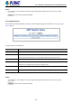
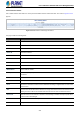
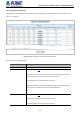
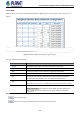
Table Of Contents
- 1. INTRODUCTION
- 2. INSTALLATION
- 3. SWITCH MANAGEMENT
- 4. WEB CONFIGURATION
- 4.1 Main Web Page
- 4.2 System
- 4.2.1 Management
- 4.2.1.1 System Information
- 4.2.1.2 IP Configuration
- 4.2.1.3 IP Status
- 4.2.1.4 Users Configuration
- 4.2.1.5 Privilege Levels
- 4.2.1.6 NTP Configuration
- 4.2.1.6.1 System Time Correction Manually
- 4.2.1.7 Time Configuration
- 4.2.1.8 UPnP
- 4.2.1.9 DHCP Relay
- 4.2.1.10 DHCP Relay Statistics
- 4.2.1.11 CPU Load
- 4.2.1.12 System Log
- 4.2.1.13 Detailed Log
- 4.2.1.14 Remote Syslog
- 4.2.1.15 SMTP Configuration
- 4.2.2 Simple Network Management Protocol
- 4.2.3 RMON
- 4.2.4 DHCP server
- 4.2.1 Management
- 4.3 Switching
- 4.3.1 Port Management
- 4.3.2 Link Aggregation
- 4.3.3 VLAN
- 4.3.3.1 VLAN Overview
- 4.3.3.2 IEEE 802.1Q VLAN
- 4.3.3.3 VLAN Port Configuration
- 4.3.3.4 VLAN Membership Status
- 4.3.3.5 VLAN Port Status
- 4.3.3.6 Private VLAN
- 4.3.3.7 Port Isolation
- 4.3.3.8 VLAN setting example:
- 4.3.3.8.1 Two Separate 802.1Q VLANs
- 4.3.3.8.2 VLAN Trunking between two 802.1Q aware switches
- 4.3.3.8.3 Port Isolate
- 4.3.3.9 MAC-based VLAN
- 4.3.3.10 Protocol-based VLAN
- 4.3.3.11 Protocol-based VLAN Membership
- 4.3.4 Spanning Tree Protocol
- 4.3.5 IGMP Snooping
- 4.3.6 MLD Snooping
- 4.3.7 MVR (Multicast VLAN Registration)
- 4.3.8 LLDP
- 4.3.9 MAC Address Table
- 4.3.10 Loop Protection
- 4.3.11 UDLD
- 4.3.12 GVRP
- 4.3.13 Link OAM
- 4.4 Routing
- 4.5 Quality of Service
- 4.6 Security
- 4.7 Power over Ethernet
- 4.8 Ring
- 4.9 ONVIF
- 4.10 Maintenance
- 5. SWITCH OPERATION
- 6. TROUBLESHOOTING
- APPENDIX A: Networking Connection
- APPENDIX B : GLOSSARY

User’s Manual of GS-5220 PoE Series Managed Switch
272
4.4.4.12 Interface Status
This is OSPF interface status table. It is used to provide the OSPF interface status information. The screen in Figure 4-4-4-12
appears.
Figure 4-4-4-12: Interface Status Page Screenshot
The page includes the following fields:
Object Description
Interface Interface identification.
Interface Address IPv4 network address.
Area ID The OSPF area ID.
Router ID The OSPF router ID.
State The state of the link.
DR ID The router ID of DR.
DR Address The IP address of DR.
BDR ID The router ID of BDR.
BDR Address The IP address of BDR.
Priority The OSPF priority. It helps determine the DR and BDR on the network to which this interface is
connected.
Cost The cost of the interface.
Hello Hello timer. A time interval that a router sends an OSPF hello packet.
Dead Dead timer. Dead timer is a time interval to wait before declaring a neighbor dead. The unit of time
is the second.
Wait
This interval is used in Wait Timer. Wait timer is a single shot timer that causes the interface to exit
waiting and select a DR on the network. Wait Time interval is the same as Dead time interval.
Retransmit
Retransmit timer. A time interval to wait before retransmitting a database description packet when
it has not been acknowledged.
Hello Timer Hello due timer. An OSPF hello packet will be sent on this interface after this due time.
Nbr Count Neighbor count. This is the number of OSPF neighbors discovered on this interface.