
GS-5220-Series (V4) User Manual
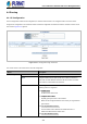
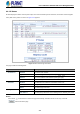
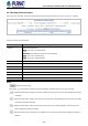
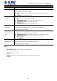
Table Of Contents
- 1. INTRODUCTION
- 2. INSTALLATION
- 3. SWITCH MANAGEMENT
- 4. WEB CONFIGURATION
- 4.1 Main Web Page
- 4.2 System
- 4.2.1 Management
- 4.2.1.1 System Information
- 4.2.1.2 IP Configuration
- 4.2.1.3 IP Status
- 4.2.1.4 Users Configuration
- 4.2.1.5 Privilege Levels
- 4.2.1.6 NTP Configuration
- 4.2.1.6.1 System Time Correction Manually
- 4.2.1.7 Time Configuration
- 4.2.1.8 UPnP
- 4.2.1.9 DHCP Relay
- 4.2.1.10 DHCP Relay Statistics
- 4.2.1.11 CPU Load
- 4.2.1.12 System Log
- 4.2.1.13 Detailed Log
- 4.2.1.14 Remote Syslog
- 4.2.1.15 SMTP Configuration
- 4.2.2 Simple Network Management Protocol
- 4.2.3 RMON
- 4.2.4 DHCP server
- 4.2.1 Management
- 4.3 Switching
- 4.3.1 Port Management
- 4.3.2 Link Aggregation
- 4.3.3 VLAN
- 4.3.3.1 VLAN Overview
- 4.3.3.2 IEEE 802.1Q VLAN
- 4.3.3.3 VLAN Port Configuration
- 4.3.3.4 VLAN Membership Status
- 4.3.3.5 VLAN Port Status
- 4.3.3.6 Private VLAN
- 4.3.3.7 Port Isolation
- 4.3.3.8 VLAN setting example:
- 4.3.3.8.1 Two Separate 802.1Q VLANs
- 4.3.3.8.2 VLAN Trunking between two 802.1Q aware switches
- 4.3.3.8.3 Port Isolate
- 4.3.3.9 MAC-based VLAN
- 4.3.3.10 Protocol-based VLAN
- 4.3.3.11 Protocol-based VLAN Membership
- 4.3.4 Spanning Tree Protocol
- 4.3.5 IGMP Snooping
- 4.3.6 MLD Snooping
- 4.3.7 MVR (Multicast VLAN Registration)
- 4.3.8 LLDP
- 4.3.9 MAC Address Table
- 4.3.10 Loop Protection
- 4.3.11 UDLD
- 4.3.12 GVRP
- 4.3.13 Link OAM
- 4.4 Routing
- 4.5 Quality of Service
- 4.6 Security
- 4.7 Power over Ethernet
- 4.8 Ring
- 4.9 ONVIF
- 4.10 Maintenance
- 5. SWITCH OPERATION
- 6. TROUBLESHOOTING
- APPENDIX A: Networking Connection
- APPENDIX B : GLOSSARY

User’s Manual of GS-5220 PoE Series Managed Switch
256
4.4.3 Routing Information Base
This is IPv4 route entry table. It is used to provide the route entries status information. The screen in Figure 4-2-3 appears.
Figure 4-2-3: IP Status Page Screenshot
The page includes the following fields:
Object Description
Protocol The protocol of the route.
DHCP: The route is created by DHCP.
Connected: The destination network is connected directly.
Static: The route is created by user.
OSPF: The route is created by OSPF.
Network/Prefix Network and prefix (example 10.0.0.0/16) of the given route entry.
NextHop The IP address of nexthop. Value '0.0.0.0' indicates the link is directly connected.
Distance The distance of the route.
Metric The metric of the route.
Interface The interface where the ip packet is outgoing.
Uptime (hh:ss:mm) The time till the route is created. The unit is second.
State Indicate if the destination network is reachable or not.
Buttons
: Click to refresh the page
Auto-refresh : Check this box to refresh the page automatically. Automatic refresh occurs every 3 seconds.
Updates the table entries, starting from the first available entry. If the first entry of the table is displayed, the button
is disabled.
Updates the table entries, ending at the entry prior to the first entry currently displayed. If the first entry of the table
is displayed, the button is disabled.
Updates the table entries, starting from the entry next to the last entry currently displayed. If the last entry of the
table is displayed, the button is disabled.
Updates the table entries, ending at the last available entry. If the last entry of the table is displayed, the button is
disabled..