
GS-5220-Series (V4) User Manual
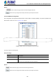
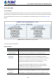
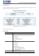
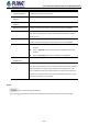
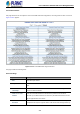
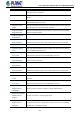
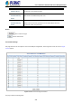
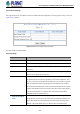
Table Of Contents
- 1. INTRODUCTION
- 2. INSTALLATION
- 3. SWITCH MANAGEMENT
- 4. WEB CONFIGURATION
- 4.1 Main Web Page
- 4.2 System
- 4.2.1 Management
- 4.2.1.1 System Information
- 4.2.1.2 IP Configuration
- 4.2.1.3 IP Status
- 4.2.1.4 Users Configuration
- 4.2.1.5 Privilege Levels
- 4.2.1.6 NTP Configuration
- 4.2.1.6.1 System Time Correction Manually
- 4.2.1.7 Time Configuration
- 4.2.1.8 UPnP
- 4.2.1.9 DHCP Relay
- 4.2.1.10 DHCP Relay Statistics
- 4.2.1.11 CPU Load
- 4.2.1.12 System Log
- 4.2.1.13 Detailed Log
- 4.2.1.14 Remote Syslog
- 4.2.1.15 SMTP Configuration
- 4.2.2 Simple Network Management Protocol
- 4.2.3 RMON
- 4.2.4 DHCP server
- 4.2.1 Management
- 4.3 Switching
- 4.3.1 Port Management
- 4.3.2 Link Aggregation
- 4.3.3 VLAN
- 4.3.3.1 VLAN Overview
- 4.3.3.2 IEEE 802.1Q VLAN
- 4.3.3.3 VLAN Port Configuration
- 4.3.3.4 VLAN Membership Status
- 4.3.3.5 VLAN Port Status
- 4.3.3.6 Private VLAN
- 4.3.3.7 Port Isolation
- 4.3.3.8 VLAN setting example:
- 4.3.3.8.1 Two Separate 802.1Q VLANs
- 4.3.3.8.2 VLAN Trunking between two 802.1Q aware switches
- 4.3.3.8.3 Port Isolate
- 4.3.3.9 MAC-based VLAN
- 4.3.3.10 Protocol-based VLAN
- 4.3.3.11 Protocol-based VLAN Membership
- 4.3.4 Spanning Tree Protocol
- 4.3.5 IGMP Snooping
- 4.3.6 MLD Snooping
- 4.3.7 MVR (Multicast VLAN Registration)
- 4.3.8 LLDP
- 4.3.9 MAC Address Table
- 4.3.10 Loop Protection
- 4.3.11 UDLD
- 4.3.12 GVRP
- 4.3.13 Link OAM
- 4.4 Routing
- 4.5 Quality of Service
- 4.6 Security
- 4.7 Power over Ethernet
- 4.8 Ring
- 4.9 ONVIF
- 4.10 Maintenance
- 5. SWITCH OPERATION
- 6. TROUBLESHOOTING
- APPENDIX A: Networking Connection
- APPENDIX B : GLOSSARY

User’s Manual of GS-5220 PoE Series Managed Switch
249
General Settings
Object Description
• Port
The switch port number.
• OAM Enabled
Controls whether Link OAM is enabled on this switch port. Enabling Link OAM
provides the network operators the ability to monitor the health of the network and
quickly determine the location of failing links or fault conditions.
• OAM Mode
Configures the OAM Mode as Active or Passive. The default mode is Passive.
Active mode
DTE's configured in Active mode initiate the exchange of Information
OAMPDUs as defined by the Discovery process. Once the Discovery process
completes, Active DTE's are permitted to send any OAMPDU while
connected to a remote OAM peer entity in Active mode. Active DTE's operate
in a limited respect if the remote OAM entity is operating in Passive mode.
Active devices should not respond to OAM remote loopback commands and
variable requests from a Passive peer.
Passive mode
DTE's configured in Passive mode do not initiate the Discovery process.
Passive DTE's react to the initiation of the Discovery process by the remote
DTE. This eliminates the possibility of passive to passive links. Passive DTE's
shall not send Variable Request or Loopback Control OAMPDUs.
• Loopback Support
Controls whether the loopback support is enabled for the switch port. Link OAM
remote loopback can be used for fault localization and link performance testing.
Enabling the loopback support will allow the DTE to execute the remote loopback
command that helps in the fault detection.
• Link Monitor Support
Controls whether the Link Monitor support is enabled for the switch port. On enabling
the Link Monitor support, the DTE supports event notification that permits the
inclusion of diagnostic information.
• MIB Retrieval Support
Controls whether the MIB Retrieval Support is enabled for the switch port. On
enabling the MIB retrieval support, the DTE supports polling of various Link OAM
based MIB variables' contents.
• Loopback Operation
If the Loopback support is enabled, enabling this field will start a loopback operation
for the port.
Buttons
Click to save changes.
: Click to undo any changes made locally and revert to previously saved values.