
GS-5220-Series (V4) User Manual
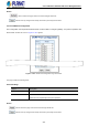
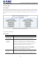
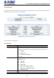
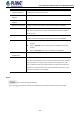
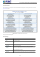
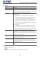
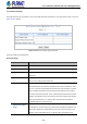
Table Of Contents
- 1. INTRODUCTION
- 2. INSTALLATION
- 3. SWITCH MANAGEMENT
- 4. WEB CONFIGURATION
- 4.1 Main Web Page
- 4.2 System
- 4.2.1 Management
- 4.2.1.1 System Information
- 4.2.1.2 IP Configuration
- 4.2.1.3 IP Status
- 4.2.1.4 Users Configuration
- 4.2.1.5 Privilege Levels
- 4.2.1.6 NTP Configuration
- 4.2.1.6.1 System Time Correction Manually
- 4.2.1.7 Time Configuration
- 4.2.1.8 UPnP
- 4.2.1.9 DHCP Relay
- 4.2.1.10 DHCP Relay Statistics
- 4.2.1.11 CPU Load
- 4.2.1.12 System Log
- 4.2.1.13 Detailed Log
- 4.2.1.14 Remote Syslog
- 4.2.1.15 SMTP Configuration
- 4.2.2 Simple Network Management Protocol
- 4.2.3 RMON
- 4.2.4 DHCP server
- 4.2.1 Management
- 4.3 Switching
- 4.3.1 Port Management
- 4.3.2 Link Aggregation
- 4.3.3 VLAN
- 4.3.3.1 VLAN Overview
- 4.3.3.2 IEEE 802.1Q VLAN
- 4.3.3.3 VLAN Port Configuration
- 4.3.3.4 VLAN Membership Status
- 4.3.3.5 VLAN Port Status
- 4.3.3.6 Private VLAN
- 4.3.3.7 Port Isolation
- 4.3.3.8 VLAN setting example:
- 4.3.3.8.1 Two Separate 802.1Q VLANs
- 4.3.3.8.2 VLAN Trunking between two 802.1Q aware switches
- 4.3.3.8.3 Port Isolate
- 4.3.3.9 MAC-based VLAN
- 4.3.3.10 Protocol-based VLAN
- 4.3.3.11 Protocol-based VLAN Membership
- 4.3.4 Spanning Tree Protocol
- 4.3.5 IGMP Snooping
- 4.3.6 MLD Snooping
- 4.3.7 MVR (Multicast VLAN Registration)
- 4.3.8 LLDP
- 4.3.9 MAC Address Table
- 4.3.10 Loop Protection
- 4.3.11 UDLD
- 4.3.12 GVRP
- 4.3.13 Link OAM
- 4.4 Routing
- 4.5 Quality of Service
- 4.6 Security
- 4.7 Power over Ethernet
- 4.8 Ring
- 4.9 ONVIF
- 4.10 Maintenance
- 5. SWITCH OPERATION
- 6. TROUBLESHOOTING
- APPENDIX A: Networking Connection
- APPENDIX B : GLOSSARY

User’s Manual of GS-5220 PoE Series Managed Switch
242
4.3.13 Link OAM
4.3.13.1 Statistics
This page provides detailed OAM traffic statistics for a specific switch port. Use the port select box to select which switch port
details to display.The displayed counters represent the total number of OAM frames received and transmitted for the selected
port. Discontinuities of these counter can occur at re-initialization of the management system. as screen in Figure 4-3-13-1
appears.
Figure 4-3-13-1: Link OAM Statistic Page Screenshot
The page includes the following fields:
General Settings
Object Description
• Rx and Tx OAM
Information PDU's
The number of received and transmitted OAM Information PDU's. Discontinuities
of this counter can occur at re-initialization of the management system.
• Rx and Tx Unique
Error Event
Notification
A count of the number of unique Event OAMPDUs received and transmitted on
this interface. Event Notifications may be sent in duplicate to increase the
probability of successfully being received, given the possibility that a frame may
be lost in transit. Duplicate Event Notification transmissions are counted by
Duplicate Event Notification counters for Tx and Rx respectively.
A unique Event Notification OAMPDU is indicated as an Event Notification
OAMPDU with a Sequence Number field that is distinct from the previously
transmitted Event Notification OAMPDU Sequence Number.
• Rx and Tx Duplicate
Error Event
Notification
A count of the number of duplicate Event OAMPDUs received and transmitted on
this interface. Event Notification OAMPDUs may be sent in duplicate to increase
the probability of successfully being received, given the possibility that a frame