
GS-5220-Series (V4) User Manual
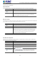
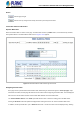
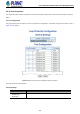
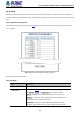

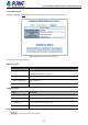
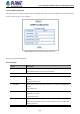
Table Of Contents
- 1. INTRODUCTION
- 2. INSTALLATION
- 3. SWITCH MANAGEMENT
- 4. WEB CONFIGURATION
- 4.1 Main Web Page
- 4.2 System
- 4.2.1 Management
- 4.2.1.1 System Information
- 4.2.1.2 IP Configuration
- 4.2.1.3 IP Status
- 4.2.1.4 Users Configuration
- 4.2.1.5 Privilege Levels
- 4.2.1.6 NTP Configuration
- 4.2.1.6.1 System Time Correction Manually
- 4.2.1.7 Time Configuration
- 4.2.1.8 UPnP
- 4.2.1.9 DHCP Relay
- 4.2.1.10 DHCP Relay Statistics
- 4.2.1.11 CPU Load
- 4.2.1.12 System Log
- 4.2.1.13 Detailed Log
- 4.2.1.14 Remote Syslog
- 4.2.1.15 SMTP Configuration
- 4.2.2 Simple Network Management Protocol
- 4.2.3 RMON
- 4.2.4 DHCP server
- 4.2.1 Management
- 4.3 Switching
- 4.3.1 Port Management
- 4.3.2 Link Aggregation
- 4.3.3 VLAN
- 4.3.3.1 VLAN Overview
- 4.3.3.2 IEEE 802.1Q VLAN
- 4.3.3.3 VLAN Port Configuration
- 4.3.3.4 VLAN Membership Status
- 4.3.3.5 VLAN Port Status
- 4.3.3.6 Private VLAN
- 4.3.3.7 Port Isolation
- 4.3.3.8 VLAN setting example:
- 4.3.3.8.1 Two Separate 802.1Q VLANs
- 4.3.3.8.2 VLAN Trunking between two 802.1Q aware switches
- 4.3.3.8.3 Port Isolate
- 4.3.3.9 MAC-based VLAN
- 4.3.3.10 Protocol-based VLAN
- 4.3.3.11 Protocol-based VLAN Membership
- 4.3.4 Spanning Tree Protocol
- 4.3.5 IGMP Snooping
- 4.3.6 MLD Snooping
- 4.3.7 MVR (Multicast VLAN Registration)
- 4.3.8 LLDP
- 4.3.9 MAC Address Table
- 4.3.10 Loop Protection
- 4.3.11 UDLD
- 4.3.12 GVRP
- 4.3.13 Link OAM
- 4.4 Routing
- 4.5 Quality of Service
- 4.6 Security
- 4.7 Power over Ethernet
- 4.8 Ring
- 4.9 ONVIF
- 4.10 Maintenance
- 5. SWITCH OPERATION
- 6. TROUBLESHOOTING
- APPENDIX A: Networking Connection
- APPENDIX B : GLOSSARY

User’s Manual of GS-5220 PoE Series Managed Switch
235
Port Configuration
Object Description
• Port
The switch port number of the port.
• Enable
Controls whether loop protection is enabled on this switch port.
• Action
Configures the action performed when a loop is detected on a port. Valid values
are Shutdown Port, Shutdown Port and Log or Log Only.
• Tx Mode
Controls whether the port is actively generating loop protection PDU's, or
whether it is just passively looking for looped PDU's.
Buttons
: Click to apply changes
: Click to undo any changes made locally and revert to previously saved values.
4.3.10.2 Loop Protection Status
This page displays the loop protection port status of the switch; screen in Figure 4-3-10-2 appears.
Figure 4-3-10-2: Loop Protection Status Screenshot
The page includes the following fields:
Object Description
• Port
The Managed Switch port number of the logical port.
• Action
The currently configured port action.
• Transmit
The currently configured port transmit mode.
• Loops
The number of loops detected on this port.
• Status
The current loop protection status of the port.
• Loop
Whether a loop is currently detected on the port.
• Time of Last Loop
The time of the last loop event detected.
Buttons
: Click to refresh the page immediately.
Auto-refresh : Check this box to enable an automatic refresh of the page at regular intervals.