
GS-5220-Series (V4) User Manual
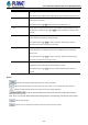
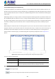
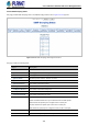
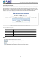
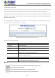
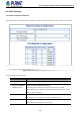
Table Of Contents
- 1. INTRODUCTION
- 2. INSTALLATION
- 3. SWITCH MANAGEMENT
- 4. WEB CONFIGURATION
- 4.1 Main Web Page
- 4.2 System
- 4.2.1 Management
- 4.2.1.1 System Information
- 4.2.1.2 IP Configuration
- 4.2.1.3 IP Status
- 4.2.1.4 Users Configuration
- 4.2.1.5 Privilege Levels
- 4.2.1.6 NTP Configuration
- 4.2.1.6.1 System Time Correction Manually
- 4.2.1.7 Time Configuration
- 4.2.1.8 UPnP
- 4.2.1.9 DHCP Relay
- 4.2.1.10 DHCP Relay Statistics
- 4.2.1.11 CPU Load
- 4.2.1.12 System Log
- 4.2.1.13 Detailed Log
- 4.2.1.14 Remote Syslog
- 4.2.1.15 SMTP Configuration
- 4.2.2 Simple Network Management Protocol
- 4.2.3 RMON
- 4.2.4 DHCP server
- 4.2.1 Management
- 4.3 Switching
- 4.3.1 Port Management
- 4.3.2 Link Aggregation
- 4.3.3 VLAN
- 4.3.3.1 VLAN Overview
- 4.3.3.2 IEEE 802.1Q VLAN
- 4.3.3.3 VLAN Port Configuration
- 4.3.3.4 VLAN Membership Status
- 4.3.3.5 VLAN Port Status
- 4.3.3.6 Private VLAN
- 4.3.3.7 Port Isolation
- 4.3.3.8 VLAN setting example:
- 4.3.3.8.1 Two Separate 802.1Q VLANs
- 4.3.3.8.2 VLAN Trunking between two 802.1Q aware switches
- 4.3.3.8.3 Port Isolate
- 4.3.3.9 MAC-based VLAN
- 4.3.3.10 Protocol-based VLAN
- 4.3.3.11 Protocol-based VLAN Membership
- 4.3.4 Spanning Tree Protocol
- 4.3.5 IGMP Snooping
- 4.3.6 MLD Snooping
- 4.3.7 MVR (Multicast VLAN Registration)
- 4.3.8 LLDP
- 4.3.9 MAC Address Table
- 4.3.10 Loop Protection
- 4.3.11 UDLD
- 4.3.12 GVRP
- 4.3.13 Link OAM
- 4.4 Routing
- 4.5 Quality of Service
- 4.6 Security
- 4.7 Power over Ethernet
- 4.8 Ring
- 4.9 ONVIF
- 4.10 Maintenance
- 5. SWITCH OPERATION
- 6. TROUBLESHOOTING
- APPENDIX A: Networking Connection
- APPENDIX B : GLOSSARY

User’s Manual of GS-5220 PoE Series Managed Switch
192
by the system. These values can be used to prioritize different classes of traffic.
The allowed range is 0 (best effort) to 7 (highest), default interface priority value is 0
• RV
Robustness Variable. The Robustness Variable allows tuning for the expected
packet loss on a network.
The allowed range is 1 to 255, default robustness variable value is 2.
• QI
Query Interval. The Query Interval is the interval between General Queries sent by
the Querier. The allowed range is 1 to 31744 seconds, default query interval is 125
seconds.
• QRI
Query Response Interval. The Max Response Time used to calculate the Max Resp
Code inserted into the periodic General Queries.
The allowed range is 0 to 31744 in tenths of seconds, default query response
interval is 100 in tenths of seconds (10 seconds).
• LLQI (LMQI for IGMP)
Last Member Query Interval. The Last Member Query Time is the time value
represented by the Last Member Query Interval, multiplied by the Last Member
Query Count.
The allowed range is 0 to 31744 in tenths of seconds, default last member query
interval is 10 in tenths of seconds (1 second).
• URI
Unsolicited Report Interval. The Unsolicited Report Interval is the time between
repetitions of a host's initial report of membership in a group.
The allowed range is 0 to 31744 seconds, default unsolicited report interval is 1
second.
Buttons
: Refreshes the displayed table starting from the "VLAN" input fields.
: Updates the table starting from the first entry in the VLAN Table, i.e. the entry with the lowest VLAN ID.
: Updates the table, starting with the entry after the last entry currently displayed.
: Click to add new IGMP VLAN. Specify the VID and configure the new entry.
Click "Save". The specific IGMP VLAN starts working after the corresponding static VLAN is also created.
: Click to apply changes
: Click to undo any changes made locally and revert to previously saved values.