
GS-5220-Series (V4) User Manual
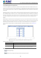
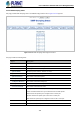

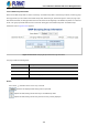
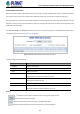
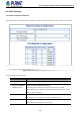
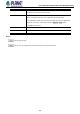
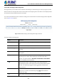
Table Of Contents
- 1. INTRODUCTION
- 2. INSTALLATION
- 3. SWITCH MANAGEMENT
- 4. WEB CONFIGURATION
- 4.1 Main Web Page
- 4.2 System
- 4.2.1 Management
- 4.2.1.1 System Information
- 4.2.1.2 IP Configuration
- 4.2.1.3 IP Status
- 4.2.1.4 Users Configuration
- 4.2.1.5 Privilege Levels
- 4.2.1.6 NTP Configuration
- 4.2.1.6.1 System Time Correction Manually
- 4.2.1.7 Time Configuration
- 4.2.1.8 UPnP
- 4.2.1.9 DHCP Relay
- 4.2.1.10 DHCP Relay Statistics
- 4.2.1.11 CPU Load
- 4.2.1.12 System Log
- 4.2.1.13 Detailed Log
- 4.2.1.14 Remote Syslog
- 4.2.1.15 SMTP Configuration
- 4.2.2 Simple Network Management Protocol
- 4.2.3 RMON
- 4.2.4 DHCP server
- 4.2.1 Management
- 4.3 Switching
- 4.3.1 Port Management
- 4.3.2 Link Aggregation
- 4.3.3 VLAN
- 4.3.3.1 VLAN Overview
- 4.3.3.2 IEEE 802.1Q VLAN
- 4.3.3.3 VLAN Port Configuration
- 4.3.3.4 VLAN Membership Status
- 4.3.3.5 VLAN Port Status
- 4.3.3.6 Private VLAN
- 4.3.3.7 Port Isolation
- 4.3.3.8 VLAN setting example:
- 4.3.3.8.1 Two Separate 802.1Q VLANs
- 4.3.3.8.2 VLAN Trunking between two 802.1Q aware switches
- 4.3.3.8.3 Port Isolate
- 4.3.3.9 MAC-based VLAN
- 4.3.3.10 Protocol-based VLAN
- 4.3.3.11 Protocol-based VLAN Membership
- 4.3.4 Spanning Tree Protocol
- 4.3.5 IGMP Snooping
- 4.3.6 MLD Snooping
- 4.3.7 MVR (Multicast VLAN Registration)
- 4.3.8 LLDP
- 4.3.9 MAC Address Table
- 4.3.10 Loop Protection
- 4.3.11 UDLD
- 4.3.12 GVRP
- 4.3.13 Link OAM
- 4.4 Routing
- 4.5 Quality of Service
- 4.6 Security
- 4.7 Power over Ethernet
- 4.8 Ring
- 4.9 ONVIF
- 4.10 Maintenance
- 5. SWITCH OPERATION
- 6. TROUBLESHOOTING
- APPENDIX A: Networking Connection
- APPENDIX B : GLOSSARY

User’s Manual of GS-5220 PoE Series Managed Switch
191
4.3.5.4 IGMP Snooping VLAN Configuration
Each page shows up to 99 entries from the VLAN table, default being 20, selected through the "entries per page" input field.
When first visited, the web page will show the first 20 entries from the beginning of the VLAN Table. The first displayed will be
the one with the lowest VLAN ID found in the VLAN Table.
The "VLAN" input fields allow the user to select the starting point in the VLAN Table. The IGMP Snooping VLAN Configuration
screen in Figure 4-3-5-8 appears.
Figure 4-3-5-8: IGMP Snooping VLAN Configuration Page Screenshot
The page includes the following fields:
Object Description
• Delete
Check to delete the entry. The designated entry will be deleted during the next save.
• VLAN ID
The VLAN ID of the entry.
• IGMP Snooping Enable
Enable the per-VLAN IGMP Snooping. Only up to 32 VLANs can be selected.
• Querier Election
Enable the IGMP Querier election in the VLAN. Disable to act as an IGMP
Non-Querier.
• Querier Address
Define the IPv4 address as source address used in IP header for IGMP Querier
election.
■ When the Querier address is not set, system uses IPv4 management address
of the IP interface associated with this VLAN.
■ When the IPv4 management address is not set, system uses the first available
IPv4 management address. Otherwise, system uses a pre-defined value.
By default, this value will be 192.0.2.1
• Compatibility
Compatibility is maintained by hosts and routers taking appropriate actions
depending on the versions of IGMP operating on hosts and routers within a network.
The allowed selection is IGMP-Auto, Forced IGMPv1, Forced IGMPv2, Forced
IGMPv3.
Default compatibility value is IGMP-Auto.
• PRI
(PRI) Priority of Interface. It indicates the IGMP control frame priority level generated