
GS-5220-Series (V4) User Manual
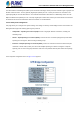
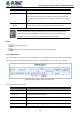
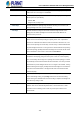
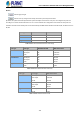
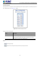
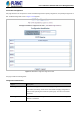
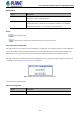
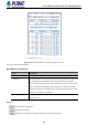
Table Of Contents
- 1. INTRODUCTION
- 2. INSTALLATION
- 3. SWITCH MANAGEMENT
- 4. WEB CONFIGURATION
- 4.1 Main Web Page
- 4.2 System
- 4.2.1 Management
- 4.2.1.1 System Information
- 4.2.1.2 IP Configuration
- 4.2.1.3 IP Status
- 4.2.1.4 Users Configuration
- 4.2.1.5 Privilege Levels
- 4.2.1.6 NTP Configuration
- 4.2.1.6.1 System Time Correction Manually
- 4.2.1.7 Time Configuration
- 4.2.1.8 UPnP
- 4.2.1.9 DHCP Relay
- 4.2.1.10 DHCP Relay Statistics
- 4.2.1.11 CPU Load
- 4.2.1.12 System Log
- 4.2.1.13 Detailed Log
- 4.2.1.14 Remote Syslog
- 4.2.1.15 SMTP Configuration
- 4.2.2 Simple Network Management Protocol
- 4.2.3 RMON
- 4.2.4 DHCP server
- 4.2.1 Management
- 4.3 Switching
- 4.3.1 Port Management
- 4.3.2 Link Aggregation
- 4.3.3 VLAN
- 4.3.3.1 VLAN Overview
- 4.3.3.2 IEEE 802.1Q VLAN
- 4.3.3.3 VLAN Port Configuration
- 4.3.3.4 VLAN Membership Status
- 4.3.3.5 VLAN Port Status
- 4.3.3.6 Private VLAN
- 4.3.3.7 Port Isolation
- 4.3.3.8 VLAN setting example:
- 4.3.3.8.1 Two Separate 802.1Q VLANs
- 4.3.3.8.2 VLAN Trunking between two 802.1Q aware switches
- 4.3.3.8.3 Port Isolate
- 4.3.3.9 MAC-based VLAN
- 4.3.3.10 Protocol-based VLAN
- 4.3.3.11 Protocol-based VLAN Membership
- 4.3.4 Spanning Tree Protocol
- 4.3.5 IGMP Snooping
- 4.3.6 MLD Snooping
- 4.3.7 MVR (Multicast VLAN Registration)
- 4.3.8 LLDP
- 4.3.9 MAC Address Table
- 4.3.10 Loop Protection
- 4.3.11 UDLD
- 4.3.12 GVRP
- 4.3.13 Link OAM
- 4.4 Routing
- 4.5 Quality of Service
- 4.6 Security
- 4.7 Power over Ethernet
- 4.8 Ring
- 4.9 ONVIF
- 4.10 Maintenance
- 5. SWITCH OPERATION
- 6. TROUBLESHOOTING
- APPENDIX A: Networking Connection
- APPENDIX B : GLOSSARY

User’s Manual of GS-5220 PoE Series Managed Switch
179
MSTI Mapping
Object Description
• MSTI
The bridge instance. The CIST is not available for explicit mapping, as it will
receive the VLANs not explicitly mapped.
• VLANs Mapped
The list of VLAN's mapped to the MSTI. The VLANs must be separated with
comma and/or space. A VLAN can only be mapped to one MSTI. A unused MSTI
should just be left empty. (I.e. not having any VLANs mapped to it.)
Buttons
: Click to apply changes
: Click to undo any changes made locally and revert to previously saved values.
4.3.4.7 MSTI Ports Configuration
This page allows the user to inspect the current STP MSTI port configurations, and possibly change them as well. A MSTI port
is a virtual port, which is instantiated separately for each active CIST (physical) port for each MSTI instance configured and
applicable for the port. The MSTI instance must be selected before displaying actual MSTI port configuration options.
This page contains MSTI port settings for physical and aggregated ports. The aggregation settings are global. The MSTI Port
Configuration screen in Figure 4-3-4-9 & Figure 4-3-4-10 appears.
Figure 4-3-4-9 : MSTI Port Configuration Page Screenshot
The page includes the following fields:
MSTI Port Configuration
Object Description
• Select MSTI
Select the bridge instance and set more detail configuration.