
GS-5220-Series (V4) User Manual
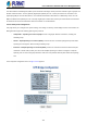
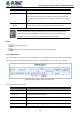
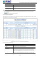
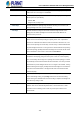
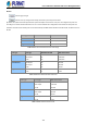
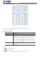
Table Of Contents
- 1. INTRODUCTION
- 2. INSTALLATION
- 3. SWITCH MANAGEMENT
- 4. WEB CONFIGURATION
- 4.1 Main Web Page
- 4.2 System
- 4.2.1 Management
- 4.2.1.1 System Information
- 4.2.1.2 IP Configuration
- 4.2.1.3 IP Status
- 4.2.1.4 Users Configuration
- 4.2.1.5 Privilege Levels
- 4.2.1.6 NTP Configuration
- 4.2.1.6.1 System Time Correction Manually
- 4.2.1.7 Time Configuration
- 4.2.1.8 UPnP
- 4.2.1.9 DHCP Relay
- 4.2.1.10 DHCP Relay Statistics
- 4.2.1.11 CPU Load
- 4.2.1.12 System Log
- 4.2.1.13 Detailed Log
- 4.2.1.14 Remote Syslog
- 4.2.1.15 SMTP Configuration
- 4.2.2 Simple Network Management Protocol
- 4.2.3 RMON
- 4.2.4 DHCP server
- 4.2.1 Management
- 4.3 Switching
- 4.3.1 Port Management
- 4.3.2 Link Aggregation
- 4.3.3 VLAN
- 4.3.3.1 VLAN Overview
- 4.3.3.2 IEEE 802.1Q VLAN
- 4.3.3.3 VLAN Port Configuration
- 4.3.3.4 VLAN Membership Status
- 4.3.3.5 VLAN Port Status
- 4.3.3.6 Private VLAN
- 4.3.3.7 Port Isolation
- 4.3.3.8 VLAN setting example:
- 4.3.3.8.1 Two Separate 802.1Q VLANs
- 4.3.3.8.2 VLAN Trunking between two 802.1Q aware switches
- 4.3.3.8.3 Port Isolate
- 4.3.3.9 MAC-based VLAN
- 4.3.3.10 Protocol-based VLAN
- 4.3.3.11 Protocol-based VLAN Membership
- 4.3.4 Spanning Tree Protocol
- 4.3.5 IGMP Snooping
- 4.3.6 MLD Snooping
- 4.3.7 MVR (Multicast VLAN Registration)
- 4.3.8 LLDP
- 4.3.9 MAC Address Table
- 4.3.10 Loop Protection
- 4.3.11 UDLD
- 4.3.12 GVRP
- 4.3.13 Link OAM
- 4.4 Routing
- 4.5 Quality of Service
- 4.6 Security
- 4.7 Power over Ethernet
- 4.8 Ring
- 4.9 ONVIF
- 4.10 Maintenance
- 5. SWITCH OPERATION
- 6. TROUBLESHOOTING
- APPENDIX A: Networking Connection
- APPENDIX B : GLOSSARY

User’s Manual of GS-5220 PoE Series Managed Switch
172
The page includes the following fields:
Basic Settings
Object Description
• Protocol Version
The STP protocol version setting. Valid values are:
STP (IEEE 802.1D Spanning Tree Protocol)
RSTP (IEEE 802.2w Rapid Spanning Tree Protocol)
MSTP (IEEE 802.1s Multiple Spanning Tree Protocol)
• Bridge Priority
Controls the bridge priority. Lower numeric values have better priority. The bridge
priority plus the MSTI instance number, concatenated with the 6-byte MAC
address of the switch forms a Bridge Identifier.
For MSTP operation, this is the priority of the CIST. Otherwise, this is the priority
of the STP/RSTP bridge.
• Hello Time
The interval between sending STP BPDU's. Valid values are in the range 1 to 10
seconds, default is 2 seconds
• Forward Delay
The delay used by STP Bridges to transition Root and Designated Ports to
Forwarding (used in STP compatible mode). Valid values are in the range 4 to 30
seconds
-Default: 15
-Minimum: The higher of 4 or [(Max. Message Age / 2) + 1]
-Maximum: 30
• Max Age
The maximum age of the information transmitted by the Bridge when it is the
Root Bridge. Valid values are in the range 6 to 40 seconds.
-Default: 20
-Minimum: The higher of 6 or [2 x (Hello Time + 1)].
-Maximum: The lower of 40 or [2 x (Forward Delay -1)]
• Maximum Hop Count
This defines the initial value of remaining Hops for MSTI information generated at
the boundary of an MSTI region. It defines how many bridges a root bridge can
distribute its BPDU information. Valid values are in the range 6 to 40 hops.
• Transmit Hold Count
The number of BPDU's a bridge port can send per second. When exceeded,
transmission of the next BPDU will be delayed. Valid values are in the range 1 to
10 BPDU's per second.
Advanced Settings
Object Description
• Edge Port BPDU
Filtering
Control whether a port explicitly configured as Edge will transmit and receive
BPDUs.
• Edge Port BPDU Guard
Control whether a port explicitly configured as Edge will disable itself upon
reception of a BPDU. The port will enter the error-disabled state, and will be