
GS-5220-Series (V4) User Manual
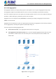
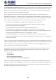
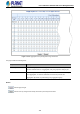
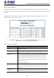
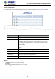

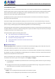
Table Of Contents
- 1. INTRODUCTION
- 2. INSTALLATION
- 3. SWITCH MANAGEMENT
- 4. WEB CONFIGURATION
- 4.1 Main Web Page
- 4.2 System
- 4.2.1 Management
- 4.2.1.1 System Information
- 4.2.1.2 IP Configuration
- 4.2.1.3 IP Status
- 4.2.1.4 Users Configuration
- 4.2.1.5 Privilege Levels
- 4.2.1.6 NTP Configuration
- 4.2.1.6.1 System Time Correction Manually
- 4.2.1.7 Time Configuration
- 4.2.1.8 UPnP
- 4.2.1.9 DHCP Relay
- 4.2.1.10 DHCP Relay Statistics
- 4.2.1.11 CPU Load
- 4.2.1.12 System Log
- 4.2.1.13 Detailed Log
- 4.2.1.14 Remote Syslog
- 4.2.1.15 SMTP Configuration
- 4.2.2 Simple Network Management Protocol
- 4.2.3 RMON
- 4.2.4 DHCP server
- 4.2.1 Management
- 4.3 Switching
- 4.3.1 Port Management
- 4.3.2 Link Aggregation
- 4.3.3 VLAN
- 4.3.3.1 VLAN Overview
- 4.3.3.2 IEEE 802.1Q VLAN
- 4.3.3.3 VLAN Port Configuration
- 4.3.3.4 VLAN Membership Status
- 4.3.3.5 VLAN Port Status
- 4.3.3.6 Private VLAN
- 4.3.3.7 Port Isolation
- 4.3.3.8 VLAN setting example:
- 4.3.3.8.1 Two Separate 802.1Q VLANs
- 4.3.3.8.2 VLAN Trunking between two 802.1Q aware switches
- 4.3.3.8.3 Port Isolate
- 4.3.3.9 MAC-based VLAN
- 4.3.3.10 Protocol-based VLAN
- 4.3.3.11 Protocol-based VLAN Membership
- 4.3.4 Spanning Tree Protocol
- 4.3.5 IGMP Snooping
- 4.3.6 MLD Snooping
- 4.3.7 MVR (Multicast VLAN Registration)
- 4.3.8 LLDP
- 4.3.9 MAC Address Table
- 4.3.10 Loop Protection
- 4.3.11 UDLD
- 4.3.12 GVRP
- 4.3.13 Link OAM
- 4.4 Routing
- 4.5 Quality of Service
- 4.6 Security
- 4.7 Power over Ethernet
- 4.8 Ring
- 4.9 ONVIF
- 4.10 Maintenance
- 5. SWITCH OPERATION
- 6. TROUBLESHOOTING
- APPENDIX A: Networking Connection
- APPENDIX B : GLOSSARY

User’s Manual of GS-5220 PoE Series Managed Switch
136
4.3.2.2 LACP Configuration
Link Aggregation Control Protocol (LACP) - LACP LAG negotiate Aggregated Port links with other LACP ports located on a
different device. LACP allows switches connected to each other to discover automatically whether any ports are member of the
same LAG.
This page allows the user to inspect the current LACP port configurations, and possibly change them as well. The LACP
Configuration screen in Figure 4-3-2-3 appears.
Figure 4-3-2-3 : LACP Port Configuration Page Screenshot
The page includes the following fields:
Object Description
• Port
The switch port number.
• LACP Enabled
Controls whether LACP is enabled on this switch port. LACP will form an
aggregation when 2 or more ports are connected to the same partner.
• Key
The Key value incurred by the port, range 1-65535 . The Auto setting will set the
key as appropriate by the physical link speed, 10Mb = 1, 100Mb = 2, 1Gb = 3.
Using the Specific setting, a user-defined value can be entered. Ports with the
same Key value can participate in the same aggregation group, while ports with
different keys cannot.
The default setting is “Auto”
• Role
The Role shows the LACP activity status. The Active will transmit LACP packets
each second, while Passive will wait for a LACP packet from a partner (speak if
spoken to).
• Timeout
The Timeout controls the period between BPDU transmissions. Fast will transmit
LACP packets each second, while Slow will wait for 30 seconds before sending a