
GS-5220-Series (V4) User Manual
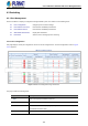

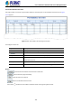
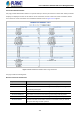
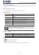
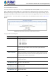
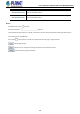
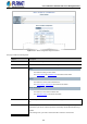
Table Of Contents
- 1. INTRODUCTION
- 2. INSTALLATION
- 3. SWITCH MANAGEMENT
- 4. WEB CONFIGURATION
- 4.1 Main Web Page
- 4.2 System
- 4.2.1 Management
- 4.2.1.1 System Information
- 4.2.1.2 IP Configuration
- 4.2.1.3 IP Status
- 4.2.1.4 Users Configuration
- 4.2.1.5 Privilege Levels
- 4.2.1.6 NTP Configuration
- 4.2.1.6.1 System Time Correction Manually
- 4.2.1.7 Time Configuration
- 4.2.1.8 UPnP
- 4.2.1.9 DHCP Relay
- 4.2.1.10 DHCP Relay Statistics
- 4.2.1.11 CPU Load
- 4.2.1.12 System Log
- 4.2.1.13 Detailed Log
- 4.2.1.14 Remote Syslog
- 4.2.1.15 SMTP Configuration
- 4.2.2 Simple Network Management Protocol
- 4.2.3 RMON
- 4.2.4 DHCP server
- 4.2.1 Management
- 4.3 Switching
- 4.3.1 Port Management
- 4.3.2 Link Aggregation
- 4.3.3 VLAN
- 4.3.3.1 VLAN Overview
- 4.3.3.2 IEEE 802.1Q VLAN
- 4.3.3.3 VLAN Port Configuration
- 4.3.3.4 VLAN Membership Status
- 4.3.3.5 VLAN Port Status
- 4.3.3.6 Private VLAN
- 4.3.3.7 Port Isolation
- 4.3.3.8 VLAN setting example:
- 4.3.3.8.1 Two Separate 802.1Q VLANs
- 4.3.3.8.2 VLAN Trunking between two 802.1Q aware switches
- 4.3.3.8.3 Port Isolate
- 4.3.3.9 MAC-based VLAN
- 4.3.3.10 Protocol-based VLAN
- 4.3.3.11 Protocol-based VLAN Membership
- 4.3.4 Spanning Tree Protocol
- 4.3.5 IGMP Snooping
- 4.3.6 MLD Snooping
- 4.3.7 MVR (Multicast VLAN Registration)
- 4.3.8 LLDP
- 4.3.9 MAC Address Table
- 4.3.10 Loop Protection
- 4.3.11 UDLD
- 4.3.12 GVRP
- 4.3.13 Link OAM
- 4.4 Routing
- 4.5 Quality of Service
- 4.6 Security
- 4.7 Power over Ethernet
- 4.8 Ring
- 4.9 ONVIF
- 4.10 Maintenance
- 5. SWITCH OPERATION
- 6. TROUBLESHOOTING
- APPENDIX A: Networking Connection
- APPENDIX B : GLOSSARY

User’s Manual of GS-5220 PoE Series Managed Switch
127
4.3.1.4 SFP Module Information
The WGSW-48040HP has supported the SFP module with digital diagnostics monitoring (DDM) function. This feature is also
known as digital optical monitoring (DOM). You can check the physical or operational status of an SFP module via the SFP
Module Information page. This page shows the operational status, such as the transceiver type, speed, wavelength, optical
output power, optical input power, temperature, laser bias current and transceiver supply voltage in real time. You can also use
the hyperlink of port no. to check the statistics on a specific interface. The SFP Module Information screen in Figure 4-3-1-4
appears.
Figure 4-3-1-4: SFP Module Information for Switch Page Screenshot
The page includes the following fields:
Object Description
• Type
Display the type of current SFP module; the possible types are:
10GBASE-SR
10GBASE-LR
1000BASE-SX
1000BASE-LX
• Speed
Display the speed of current SFP module; the speed value or description is got
from the SFP module. Different vendors SFP modules might show different
speed information.
• Wave Length (nm)
Display the wavelength of current SFP module; the wavelength value is got from
the SFP module. U
se this column to check if the wavelength values of two nodes
are matched while the fiber connection failed.
• Distance (m)
Display the support distance of current SFP module; the distance value is got
from the SFP module.
• Temperature (C)
– SFP DDM Module Only
Display the temperature of current SFP DDM module; the temperature value is
got from the SFP DDM module.
• Voltage(V)
– SFP DDM Module Only
Display the voltage of current SFP DDM module; the voltage value is got from the
SFP DDM module.
• Current(mA)
– SFP DDM Module Only
Display the Ampere of current SFP DDM module; the Ampere value is got from
the SFP DDM module.