
GS-5220-Series (V4) User Manual
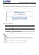

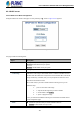
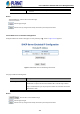
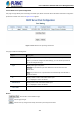
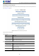
Table Of Contents
- 1. INTRODUCTION
- 2. INSTALLATION
- 3. SWITCH MANAGEMENT
- 4. WEB CONFIGURATION
- 4.1 Main Web Page
- 4.2 System
- 4.2.1 Management
- 4.2.1.1 System Information
- 4.2.1.2 IP Configuration
- 4.2.1.3 IP Status
- 4.2.1.4 Users Configuration
- 4.2.1.5 Privilege Levels
- 4.2.1.6 NTP Configuration
- 4.2.1.6.1 System Time Correction Manually
- 4.2.1.7 Time Configuration
- 4.2.1.8 UPnP
- 4.2.1.9 DHCP Relay
- 4.2.1.10 DHCP Relay Statistics
- 4.2.1.11 CPU Load
- 4.2.1.12 System Log
- 4.2.1.13 Detailed Log
- 4.2.1.14 Remote Syslog
- 4.2.1.15 SMTP Configuration
- 4.2.2 Simple Network Management Protocol
- 4.2.3 RMON
- 4.2.4 DHCP server
- 4.2.1 Management
- 4.3 Switching
- 4.3.1 Port Management
- 4.3.2 Link Aggregation
- 4.3.3 VLAN
- 4.3.3.1 VLAN Overview
- 4.3.3.2 IEEE 802.1Q VLAN
- 4.3.3.3 VLAN Port Configuration
- 4.3.3.4 VLAN Membership Status
- 4.3.3.5 VLAN Port Status
- 4.3.3.6 Private VLAN
- 4.3.3.7 Port Isolation
- 4.3.3.8 VLAN setting example:
- 4.3.3.8.1 Two Separate 802.1Q VLANs
- 4.3.3.8.2 VLAN Trunking between two 802.1Q aware switches
- 4.3.3.8.3 Port Isolate
- 4.3.3.9 MAC-based VLAN
- 4.3.3.10 Protocol-based VLAN
- 4.3.3.11 Protocol-based VLAN Membership
- 4.3.4 Spanning Tree Protocol
- 4.3.5 IGMP Snooping
- 4.3.6 MLD Snooping
- 4.3.7 MVR (Multicast VLAN Registration)
- 4.3.8 LLDP
- 4.3.9 MAC Address Table
- 4.3.10 Loop Protection
- 4.3.11 UDLD
- 4.3.12 GVRP
- 4.3.13 Link OAM
- 4.4 Routing
- 4.5 Quality of Service
- 4.6 Security
- 4.7 Power over Ethernet
- 4.8 Ring
- 4.9 ONVIF
- 4.10 Maintenance
- 5. SWITCH OPERATION
- 6. TROUBLESHOOTING
- APPENDIX A: Networking Connection
- APPENDIX B : GLOSSARY

User’s Manual of GS-5220 PoE Series Managed Switch
117
4.2.4 DHCP server
4.2.4.1 DHCP Server Mode Configuration
Configure DHCP server mode on this page. The entry index key is ID.; screen in Figure 4-2-4-1 appears.
Figure 4-2-4-1: DHCP server mode Page Screenshot
The page includes the following fields:
Object Description
• Mode
Configure the operation mode per system. Possible modes are:
Enabled: Enable DHCP server per system.
Disabled: Disable DHCP server pre system.
• VLAN Mode
Configure operation mode to enable/disable DHCP server per VLAN.
• VLAN Range
Indicate the VLAN range in which DHCP server is enabled or disabled. The first
VLAN ID must be smaller than or equal to the second VLAN ID. BUT, if the VLAN
range contains only 1 VLAN ID, then you can just input it into either one of the
first and second VLAN ID or both.
On the other hand, if you want to disable existed VLAN range, then you can
follow the steps.
1. press to add a new VLAN range.
2. 2. input the VLAN range that you want to disable.
3. 3. choose Mode to be Disabled.
4. 4. press to apply the change.
Then, you will see the disabled VLAN range is removed from the DHCP Server
mode configuration page.
• Mode Indicate the operation mode per VLAN. Possible modes are:
Enabled: Enable DHCP server per VLAN.