
GS-5220-Series User Manual
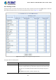
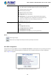
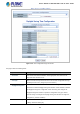
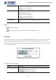
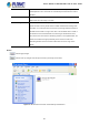
Table Of Contents
- 1. INTRODUCTION
- 2. INSTALLATION
- 3. SWITCH MANAGEMENT
- 4. WEB CONFIGURATION
- 4.1 Main Web Page
- 4.2 System
- 4.2.1 System Information
- 4.2.2 IP Configuration
- 4.2.3 IP Status
- 4.2.4 Users Configuration
- 4.2.5 Privilege Levels
- 4.2.6 NTP Configuration
- 4.2.7 Time Configuration
- 4.2.8 UPnP
- 4.2.9 DHCP Relay
- 4.2.10 DHCP Relay Statistics
- 4.2.11 CPU Load
- 4.2.12 System Log
- 4.2.13 Detailed Log
- 4.2.14 Remote Syslog
- 4.2.15 SMTP Configuration
- 4.2.16 Web Firmware Upgrade
- 4.2.17 TFTP Firmware Upgrade
- 4.2.18 Save Startup Config
- 4.2.19 Configuration Download
- 4.2.20 Configuration Upload
- 4.2.21 Configure Activate
- 4.2.22 Configure Delete
- 4.2.23 Image Select
- 4.2.24 Factory Default
- 4.2.25 System Reboot
- 4.3 Simple Network Management Protocol
- 4.4 Port Management
- 4.5 Link Aggregation
- 4.6 VLAN
- 4.7 Spanning Tree Protocol
- 4.8 Multicast
- 4.8.1 IGMP Snooping
- 4.8.2 Profile Table
- 4.8.3 Address Entry
- 4.8.4 IGMP Snooping Configuration
- 4.8.5 IGMP Snooping VLAN Configuration
- 4.8.6 IGMP Snooping Port Group Filtering
- 4.8.7 IGMP Snooping Status
- 4.8.8 IGMP Group Information
- 4.8.9 IGMPv3 Information
- 4.8.10 MLD Snooping Configuration
- 4.8.11 MLD Snooping VLAN Configuration
- 4.8.12 MLD Snooping Port Group Filtering
- 4.8.13 MLD Snooping Status
- 4.8.14 MLD Group Information
- 4.8.15 MLDv2 Information
- 4.8.16 MVR (Multicast VLAN Registration)
- 4.8.17 MVR Status
- 4.8.18 MVR Groups Information
- 4.8.19 MVR SFM Information
- 4.9 Quality of Service
- 4.9.1 Understanding QoS
- 4.9.2 Port Policing
- 4.9.3 Port Classification
- 4.9.4 Port Scheduler
- 4.9.5 Port Shaping
- 4.9.6 Port Tag Remarking
- 4.9.7 Port DSCP
- 4.9.8 DSCP-based QoS
- 4.9.9 DSCP Translation
- 4.9.10 DSCP Classification
- 4.9.11 QoS Control List
- 4.9.12 QCL Status
- 4.9.13 Storm Control Configuration
- 4.9.14 WRED
- 4.9.15 QoS Statistics
- 4.9.16 Voice VLAN Configuration
- 4.9.17 Voice VLAN OUI Table
- 4.10 Access Control Lists
- 4.11 Authentication
- 4.11.1 Understanding IEEE 802.1X Port-based Authentication
- 4.11.2 Authentication Configuration
- 4.11.3 Network Access Server Configuration
- 4.11.4 Network Access Overview
- 4.11.5 Network Access Statistics
- 4.11.6 RADIUS
- 4.11.7 TACACS+
- 4.11.8 RADIUS Overview
- 4.11.9 RADIUS Details
- 4.11.10 Windows Platform RADIUS Server Configuration
- 4.11.11 802.1X Client Configuration
- 4.12 Security
- 4.12.1 Port Limit Control
- 4.12.2 Access Management
- 4.12.3 Access Management Statistics
- 4.12.4 HTTPs
- 4.12.5 SSH
- 4.12.6 Port Security Status
- 4.12.7 Port Security Detail
- 4.12.8 DHCP Snooping
- 4.12.9 Snooping Table
- 4.12.10 IP Source Guard Configuration
- 4.12.11 IP Source Guard Static Table
- 4.12.12 ARP Inspection
- 4.12.13 ARP Inspection Static Table
- 4.12.14 Dynamic ARP Inspection Table
- 4.13 Address Table
- 4.14 LLDP
- 4.15 Network Diagnostics
- 4.16 Power over Ethernet
- 4.17 Loop Protection
- 4.18 RMON
- 4.19 ONVIF
- 5. SWITCH OPERATION
- 6. TROUBLESHOOTING
- APPENDIX A: Networking Connection
- APPENDIX B : GLOSSARY

User’s Manual of GS-5220 Ultra PoE & PoE+ Series
87
When the mode is enabled, two ACEs are added automatically to trap UPnP
related packets to CPU. The ACEs are automatically removed when the mode is
disabled.
• TTL
The TTL value is used by UPnP to send SSDP advertisement messages.
Valid values are in the range of 1 to 255.
• Advertising Duration
The duration, carried in SSDP packets, is used to inform a control point or control
points how often it or they should receive a SSDP advertisement message from
this switch. If a control point does not receive any message within the duration, it
will think that the switch no longer exists. Due to the unreliable nature of UDP, in
the standard it is recommended that such refreshing of advertisements to be
done at less than one-half of the advertising duration. In the implementation, the
switch sends SSDP messages periodically at the interval one-half of the
advertising duration minus 30 seconds. Valid values are in the range 100 to
86400.
Buttons
: Click to apply changes
: Click to undo any changes made locally and revert to previously saved values.
Figure 4-2-11: UPnP
devices Shown on Windows My Network Place