
GS-5220-Series User Manual
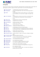
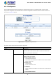
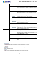
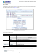
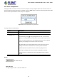
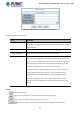
Table Of Contents
- 1. INTRODUCTION
- 2. INSTALLATION
- 3. SWITCH MANAGEMENT
- 4. WEB CONFIGURATION
- 4.1 Main Web Page
- 4.2 System
- 4.2.1 System Information
- 4.2.2 IP Configuration
- 4.2.3 IP Status
- 4.2.4 Users Configuration
- 4.2.5 Privilege Levels
- 4.2.6 NTP Configuration
- 4.2.7 Time Configuration
- 4.2.8 UPnP
- 4.2.9 DHCP Relay
- 4.2.10 DHCP Relay Statistics
- 4.2.11 CPU Load
- 4.2.12 System Log
- 4.2.13 Detailed Log
- 4.2.14 Remote Syslog
- 4.2.15 SMTP Configuration
- 4.2.16 Web Firmware Upgrade
- 4.2.17 TFTP Firmware Upgrade
- 4.2.18 Save Startup Config
- 4.2.19 Configuration Download
- 4.2.20 Configuration Upload
- 4.2.21 Configure Activate
- 4.2.22 Configure Delete
- 4.2.23 Image Select
- 4.2.24 Factory Default
- 4.2.25 System Reboot
- 4.3 Simple Network Management Protocol
- 4.4 Port Management
- 4.5 Link Aggregation
- 4.6 VLAN
- 4.7 Spanning Tree Protocol
- 4.8 Multicast
- 4.8.1 IGMP Snooping
- 4.8.2 Profile Table
- 4.8.3 Address Entry
- 4.8.4 IGMP Snooping Configuration
- 4.8.5 IGMP Snooping VLAN Configuration
- 4.8.6 IGMP Snooping Port Group Filtering
- 4.8.7 IGMP Snooping Status
- 4.8.8 IGMP Group Information
- 4.8.9 IGMPv3 Information
- 4.8.10 MLD Snooping Configuration
- 4.8.11 MLD Snooping VLAN Configuration
- 4.8.12 MLD Snooping Port Group Filtering
- 4.8.13 MLD Snooping Status
- 4.8.14 MLD Group Information
- 4.8.15 MLDv2 Information
- 4.8.16 MVR (Multicast VLAN Registration)
- 4.8.17 MVR Status
- 4.8.18 MVR Groups Information
- 4.8.19 MVR SFM Information
- 4.9 Quality of Service
- 4.9.1 Understanding QoS
- 4.9.2 Port Policing
- 4.9.3 Port Classification
- 4.9.4 Port Scheduler
- 4.9.5 Port Shaping
- 4.9.6 Port Tag Remarking
- 4.9.7 Port DSCP
- 4.9.8 DSCP-based QoS
- 4.9.9 DSCP Translation
- 4.9.10 DSCP Classification
- 4.9.11 QoS Control List
- 4.9.12 QCL Status
- 4.9.13 Storm Control Configuration
- 4.9.14 WRED
- 4.9.15 QoS Statistics
- 4.9.16 Voice VLAN Configuration
- 4.9.17 Voice VLAN OUI Table
- 4.10 Access Control Lists
- 4.11 Authentication
- 4.11.1 Understanding IEEE 802.1X Port-based Authentication
- 4.11.2 Authentication Configuration
- 4.11.3 Network Access Server Configuration
- 4.11.4 Network Access Overview
- 4.11.5 Network Access Statistics
- 4.11.6 RADIUS
- 4.11.7 TACACS+
- 4.11.8 RADIUS Overview
- 4.11.9 RADIUS Details
- 4.11.10 Windows Platform RADIUS Server Configuration
- 4.11.11 802.1X Client Configuration
- 4.12 Security
- 4.12.1 Port Limit Control
- 4.12.2 Access Management
- 4.12.3 Access Management Statistics
- 4.12.4 HTTPs
- 4.12.5 SSH
- 4.12.6 Port Security Status
- 4.12.7 Port Security Detail
- 4.12.8 DHCP Snooping
- 4.12.9 Snooping Table
- 4.12.10 IP Source Guard Configuration
- 4.12.11 IP Source Guard Static Table
- 4.12.12 ARP Inspection
- 4.12.13 ARP Inspection Static Table
- 4.12.14 Dynamic ARP Inspection Table
- 4.13 Address Table
- 4.14 LLDP
- 4.15 Network Diagnostics
- 4.16 Power over Ethernet
- 4.17 Loop Protection
- 4.18 RMON
- 4.19 ONVIF
- 5. SWITCH OPERATION
- 6. TROUBLESHOOTING
- APPENDIX A: Networking Connection
- APPENDIX B : GLOSSARY

User’s Manual of GS-5220 Ultra PoE & PoE+ Series
77
Specify from which DHCP-enabled interface a provided DNS server
should be preferred.
DNS Proxy
When DNS proxy is enabled, system will relay DNS requests to the
currently configured DNS server, and reply as a DNS resolver to the client
devices on the network.
• IP Address Delete
Select this option to delete an existing IP interface.
VLAN
The VLAN associated with the IP interface. Only ports in this VLAN will be
able to access the IP interface. This field is only available for input when
creating a new interface.
IPv4
DHCP
Enabled
Enable the DHCP client by checking this box.
Fallback
The number of seconds for trying to obtain a DHCP lease.
Current Lease
For DHCP interfaces with an active lease, this column shows the current
interface address, as provided by the DHCP server.
IPv4 Address
Provide the IP address of this Managed Switch in dotted decimal notation.
Mask Length
The IPv4 network mask, in number of bits (prefix length). Valid values are
between 0 and 30 bits for a IPv4 address.
IPv6 Address
Provide the IP address of this Managed Switch. An IPv6 address is in
128-bit records represented as eight fields of up to four hexadecimal
digits with a colon separating each field (:).
Mask Length
The IPv6 network mask, in number of bits (prefix length). Valid values are
between 1 and 128 bits for an IPv6 address.
• IP Routes Delete
Select this option to delete an existing IP route.
Network
The destination IP network or host address of this route. Valid format is
dotted decimal notation or a valid IPv6 notation. A default route can use
the value 0.0.0.0 or IPv6 :: notation.
Mask Length
The destination IP network or host mask, in number of bits (prefix length).
Gateway
The IP address of the IP gateway. Valid format is dotted decimal notation
or a valid IPv6 notation. Gateway and Network must be of the same type.
Next Hop VLAN
The VLAN ID (VID) of the specific IPv6 interface associated with the
gateway.
Buttons
: Click to add a new IP interface. A maximum of 128 interfaces are supported.
: Click to add a new IP route. A maximum of 32 routes are supported.
: Click to apply changes.
: Click to undo any changes made locally and revert to previously saved values.