
GS-5220-Series User Manual
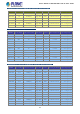
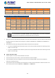
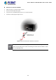
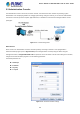
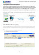
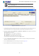
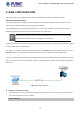
Table Of Contents
- 1. INTRODUCTION
- 2. INSTALLATION
- 3. SWITCH MANAGEMENT
- 4. WEB CONFIGURATION
- 4.1 Main Web Page
- 4.2 System
- 4.2.1 System Information
- 4.2.2 IP Configuration
- 4.2.3 IP Status
- 4.2.4 Users Configuration
- 4.2.5 Privilege Levels
- 4.2.6 NTP Configuration
- 4.2.7 Time Configuration
- 4.2.8 UPnP
- 4.2.9 DHCP Relay
- 4.2.10 DHCP Relay Statistics
- 4.2.11 CPU Load
- 4.2.12 System Log
- 4.2.13 Detailed Log
- 4.2.14 Remote Syslog
- 4.2.15 SMTP Configuration
- 4.2.16 Web Firmware Upgrade
- 4.2.17 TFTP Firmware Upgrade
- 4.2.18 Save Startup Config
- 4.2.19 Configuration Download
- 4.2.20 Configuration Upload
- 4.2.21 Configure Activate
- 4.2.22 Configure Delete
- 4.2.23 Image Select
- 4.2.24 Factory Default
- 4.2.25 System Reboot
- 4.3 Simple Network Management Protocol
- 4.4 Port Management
- 4.5 Link Aggregation
- 4.6 VLAN
- 4.7 Spanning Tree Protocol
- 4.8 Multicast
- 4.8.1 IGMP Snooping
- 4.8.2 Profile Table
- 4.8.3 Address Entry
- 4.8.4 IGMP Snooping Configuration
- 4.8.5 IGMP Snooping VLAN Configuration
- 4.8.6 IGMP Snooping Port Group Filtering
- 4.8.7 IGMP Snooping Status
- 4.8.8 IGMP Group Information
- 4.8.9 IGMPv3 Information
- 4.8.10 MLD Snooping Configuration
- 4.8.11 MLD Snooping VLAN Configuration
- 4.8.12 MLD Snooping Port Group Filtering
- 4.8.13 MLD Snooping Status
- 4.8.14 MLD Group Information
- 4.8.15 MLDv2 Information
- 4.8.16 MVR (Multicast VLAN Registration)
- 4.8.17 MVR Status
- 4.8.18 MVR Groups Information
- 4.8.19 MVR SFM Information
- 4.9 Quality of Service
- 4.9.1 Understanding QoS
- 4.9.2 Port Policing
- 4.9.3 Port Classification
- 4.9.4 Port Scheduler
- 4.9.5 Port Shaping
- 4.9.6 Port Tag Remarking
- 4.9.7 Port DSCP
- 4.9.8 DSCP-based QoS
- 4.9.9 DSCP Translation
- 4.9.10 DSCP Classification
- 4.9.11 QoS Control List
- 4.9.12 QCL Status
- 4.9.13 Storm Control Configuration
- 4.9.14 WRED
- 4.9.15 QoS Statistics
- 4.9.16 Voice VLAN Configuration
- 4.9.17 Voice VLAN OUI Table
- 4.10 Access Control Lists
- 4.11 Authentication
- 4.11.1 Understanding IEEE 802.1X Port-based Authentication
- 4.11.2 Authentication Configuration
- 4.11.3 Network Access Server Configuration
- 4.11.4 Network Access Overview
- 4.11.5 Network Access Statistics
- 4.11.6 RADIUS
- 4.11.7 TACACS+
- 4.11.8 RADIUS Overview
- 4.11.9 RADIUS Details
- 4.11.10 Windows Platform RADIUS Server Configuration
- 4.11.11 802.1X Client Configuration
- 4.12 Security
- 4.12.1 Port Limit Control
- 4.12.2 Access Management
- 4.12.3 Access Management Statistics
- 4.12.4 HTTPs
- 4.12.5 SSH
- 4.12.6 Port Security Status
- 4.12.7 Port Security Detail
- 4.12.8 DHCP Snooping
- 4.12.9 Snooping Table
- 4.12.10 IP Source Guard Configuration
- 4.12.11 IP Source Guard Static Table
- 4.12.12 ARP Inspection
- 4.12.13 ARP Inspection Static Table
- 4.12.14 Dynamic ARP Inspection Table
- 4.13 Address Table
- 4.14 LLDP
- 4.15 Network Diagnostics
- 4.16 Power over Ethernet
- 4.17 Loop Protection
- 4.18 RMON
- 4.19 ONVIF
- 5. SWITCH OPERATION
- 6. TROUBLESHOOTING
- APPENDIX A: Networking Connection
- APPENDIX B : GLOSSARY

User’s Manual of GS-5220 Ultra PoE & PoE+ Series
62
10Gbps SFP+ (10G Ethernet/10GBASE)
Model Speed (Mbps)
Connector
Interface
Fiber Mode Distance Wavelength (nm)
Operating Temp.
MTB-SR 10G LC Multi Mode Up to 300m 850nm 0 ~ 60 degrees C
MTB-LR 10G LC Single Mode 10km 1310nm 0 ~ 60 degrees C
10Gbps SFP+ (10GBASE-BX, Single Fiber Bi-directional SFP)
Model Speed (Mbps)
Connector
Interface
Fiber Mode Distance
Wavelength (TX)
Wavelength (RX)
Operating Temp.
MTB-LA20
MTB-LB20
10G WDM(LC) Single Mode 20km 1270nm 1330nm 0 ~ 60 degrees C
10G WDM(LC) Single Mode 20km 1330nm 1270nm 0 ~ 60 degrees C
MTB-LA40
MTB-LB40
10G WDM(LC) Single Mode 40km 1270nm 1330nm 0 ~ 60 degrees C
10G WDM(LC) Single Mode 40km 1330nm 1270nm 0 ~ 60 degrees C
MTB-LA60
MTB-LB60
10G WDM(LC) Single Mode 60km 1270nm 1330nm 0 ~ 60 degrees C
10G WDM(LC) Single Mode 60km 1330nm 1270nm 0 ~ 60 degrees C
It is recommended to use PLANET SFP/SFP+ on the Managed Switch. If you insert an SFP/SFP+
transceiver that is not supported, the Managed Switch will not recognize it.
1. Before we connect the GS-5220 Ultra PoE & PoE+ series to the other network device, we have to make sure both sides of
the SFP transceivers are with the same media type, for example: 1000BASE-SX to 1000BASE-SX, 1000BASE-LX to
1000BASE-LX.
2. Check whether the fiber-optic cable type matches with the SFP transceiver requirement.
To connect to 1000BASE-SX SFP transceiver, please use the multi-mode fiber cable with one side being the male
duplex LC connector type.
To connect to 1000BASE-LX SFP transceiver, please use the single-mode fiber cable with one side being the male
duplex LC connector type.
Connect the Fiber Cable
1. Insert the duplex LC connector into the SFP/SFP+ transceiver.
2. Connect the other end of the cable to a device with SFP/SFP+ transceiver installed.
3. Check the LNK/ACT LED of the SFP/SFP+ slot on the front of the Managed Switch. Ensure that the SFP/SFP+
transceiver is operating correctly.
4. Check the Link mode of the SFP/SFP+ port if the link fails. To function with some fiber-NICs or Media Converters, user
has to set the port Link mode to “10G Force”, “1000M Force” or “100M Force”.