
GS-5220-Series User Manual
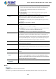
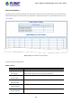
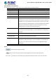
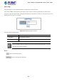
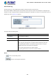
Table Of Contents
- 1. INTRODUCTION
- 2. INSTALLATION
- 3. SWITCH MANAGEMENT
- 4. WEB CONFIGURATION
- 4.1 Main Web Page
- 4.2 System
- 4.2.1 System Information
- 4.2.2 IP Configuration
- 4.2.3 IP Status
- 4.2.4 Users Configuration
- 4.2.5 Privilege Levels
- 4.2.6 NTP Configuration
- 4.2.7 Time Configuration
- 4.2.8 UPnP
- 4.2.9 DHCP Relay
- 4.2.10 DHCP Relay Statistics
- 4.2.11 CPU Load
- 4.2.12 System Log
- 4.2.13 Detailed Log
- 4.2.14 Remote Syslog
- 4.2.15 SMTP Configuration
- 4.2.16 Web Firmware Upgrade
- 4.2.17 TFTP Firmware Upgrade
- 4.2.18 Save Startup Config
- 4.2.19 Configuration Download
- 4.2.20 Configuration Upload
- 4.2.21 Configure Activate
- 4.2.22 Configure Delete
- 4.2.23 Image Select
- 4.2.24 Factory Default
- 4.2.25 System Reboot
- 4.3 Simple Network Management Protocol
- 4.4 Port Management
- 4.5 Link Aggregation
- 4.6 VLAN
- 4.7 Spanning Tree Protocol
- 4.8 Multicast
- 4.8.1 IGMP Snooping
- 4.8.2 Profile Table
- 4.8.3 Address Entry
- 4.8.4 IGMP Snooping Configuration
- 4.8.5 IGMP Snooping VLAN Configuration
- 4.8.6 IGMP Snooping Port Group Filtering
- 4.8.7 IGMP Snooping Status
- 4.8.8 IGMP Group Information
- 4.8.9 IGMPv3 Information
- 4.8.10 MLD Snooping Configuration
- 4.8.11 MLD Snooping VLAN Configuration
- 4.8.12 MLD Snooping Port Group Filtering
- 4.8.13 MLD Snooping Status
- 4.8.14 MLD Group Information
- 4.8.15 MLDv2 Information
- 4.8.16 MVR (Multicast VLAN Registration)
- 4.8.17 MVR Status
- 4.8.18 MVR Groups Information
- 4.8.19 MVR SFM Information
- 4.9 Quality of Service
- 4.9.1 Understanding QoS
- 4.9.2 Port Policing
- 4.9.3 Port Classification
- 4.9.4 Port Scheduler
- 4.9.5 Port Shaping
- 4.9.6 Port Tag Remarking
- 4.9.7 Port DSCP
- 4.9.8 DSCP-based QoS
- 4.9.9 DSCP Translation
- 4.9.10 DSCP Classification
- 4.9.11 QoS Control List
- 4.9.12 QCL Status
- 4.9.13 Storm Control Configuration
- 4.9.14 WRED
- 4.9.15 QoS Statistics
- 4.9.16 Voice VLAN Configuration
- 4.9.17 Voice VLAN OUI Table
- 4.10 Access Control Lists
- 4.11 Authentication
- 4.11.1 Understanding IEEE 802.1X Port-based Authentication
- 4.11.2 Authentication Configuration
- 4.11.3 Network Access Server Configuration
- 4.11.4 Network Access Overview
- 4.11.5 Network Access Statistics
- 4.11.6 RADIUS
- 4.11.7 TACACS+
- 4.11.8 RADIUS Overview
- 4.11.9 RADIUS Details
- 4.11.10 Windows Platform RADIUS Server Configuration
- 4.11.11 802.1X Client Configuration
- 4.12 Security
- 4.12.1 Port Limit Control
- 4.12.2 Access Management
- 4.12.3 Access Management Statistics
- 4.12.4 HTTPs
- 4.12.5 SSH
- 4.12.6 Port Security Status
- 4.12.7 Port Security Detail
- 4.12.8 DHCP Snooping
- 4.12.9 Snooping Table
- 4.12.10 IP Source Guard Configuration
- 4.12.11 IP Source Guard Static Table
- 4.12.12 ARP Inspection
- 4.12.13 ARP Inspection Static Table
- 4.12.14 Dynamic ARP Inspection Table
- 4.13 Address Table
- 4.14 LLDP
- 4.15 Network Diagnostics
- 4.16 Power over Ethernet
- 4.17 Loop Protection
- 4.18 RMON
- 4.19 ONVIF
- 5. SWITCH OPERATION
- 6. TROUBLESHOOTING
- APPENDIX A: Networking Connection
- APPENDIX B : GLOSSARY

User’s Manual of GS-5220 Ultra PoE & PoE+ Series
330
4.15.2 IPv6 Ping
This page allows you to issue ICMPv6 PING packets to troubleshoot IPv6 connectivity issues.
After you press “Start”, 5 ICMPv6 packets are transmitted, and the sequence number and roundtrip time are displayed upon
reception of a reply. The page refreshes automatically until responses to all packets are received, or until a timeout occurs. The
ICMPv6 Ping screen in Figure 4-15-2 appears.
Figure 4-15-2: ICMPv6 Ping Page Screenshot
The page includes the following fields:
Object Description
• IP Address
The destination IP Address.
• Ping Length
The payload size of the ICMP packet. Values range from 2 bytes to 1452 bytes.
• Egress Interface
The VLAN ID (VID) of the specific egress IPv6 interface which ICMP packet
goes. The given VID ranges from 1 to 4094 and will be effective only when the
corresponding IPv6 interface is valid. When the egress interface is not given,
PING6 finds the best match interface for destination.
Do not specify egress interface for loopback address.
Do specify egress interface for link-local or multicast address.
Buttons
: Click to transmit ICMP packets.
: Click to re-start diagnostics with PING.