
GS-5220-Series User Manual
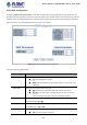

Table Of Contents
- 1. INTRODUCTION
- 2. INSTALLATION
- 3. SWITCH MANAGEMENT
- 4. WEB CONFIGURATION
- 4.1 Main Web Page
- 4.2 System
- 4.2.1 System Information
- 4.2.2 IP Configuration
- 4.2.3 IP Status
- 4.2.4 Users Configuration
- 4.2.5 Privilege Levels
- 4.2.6 NTP Configuration
- 4.2.7 Time Configuration
- 4.2.8 UPnP
- 4.2.9 DHCP Relay
- 4.2.10 DHCP Relay Statistics
- 4.2.11 CPU Load
- 4.2.12 System Log
- 4.2.13 Detailed Log
- 4.2.14 Remote Syslog
- 4.2.15 SMTP Configuration
- 4.2.16 Web Firmware Upgrade
- 4.2.17 TFTP Firmware Upgrade
- 4.2.18 Save Startup Config
- 4.2.19 Configuration Download
- 4.2.20 Configuration Upload
- 4.2.21 Configure Activate
- 4.2.22 Configure Delete
- 4.2.23 Image Select
- 4.2.24 Factory Default
- 4.2.25 System Reboot
- 4.3 Simple Network Management Protocol
- 4.4 Port Management
- 4.5 Link Aggregation
- 4.6 VLAN
- 4.7 Spanning Tree Protocol
- 4.8 Multicast
- 4.8.1 IGMP Snooping
- 4.8.2 Profile Table
- 4.8.3 Address Entry
- 4.8.4 IGMP Snooping Configuration
- 4.8.5 IGMP Snooping VLAN Configuration
- 4.8.6 IGMP Snooping Port Group Filtering
- 4.8.7 IGMP Snooping Status
- 4.8.8 IGMP Group Information
- 4.8.9 IGMPv3 Information
- 4.8.10 MLD Snooping Configuration
- 4.8.11 MLD Snooping VLAN Configuration
- 4.8.12 MLD Snooping Port Group Filtering
- 4.8.13 MLD Snooping Status
- 4.8.14 MLD Group Information
- 4.8.15 MLDv2 Information
- 4.8.16 MVR (Multicast VLAN Registration)
- 4.8.17 MVR Status
- 4.8.18 MVR Groups Information
- 4.8.19 MVR SFM Information
- 4.9 Quality of Service
- 4.9.1 Understanding QoS
- 4.9.2 Port Policing
- 4.9.3 Port Classification
- 4.9.4 Port Scheduler
- 4.9.5 Port Shaping
- 4.9.6 Port Tag Remarking
- 4.9.7 Port DSCP
- 4.9.8 DSCP-based QoS
- 4.9.9 DSCP Translation
- 4.9.10 DSCP Classification
- 4.9.11 QoS Control List
- 4.9.12 QCL Status
- 4.9.13 Storm Control Configuration
- 4.9.14 WRED
- 4.9.15 QoS Statistics
- 4.9.16 Voice VLAN Configuration
- 4.9.17 Voice VLAN OUI Table
- 4.10 Access Control Lists
- 4.11 Authentication
- 4.11.1 Understanding IEEE 802.1X Port-based Authentication
- 4.11.2 Authentication Configuration
- 4.11.3 Network Access Server Configuration
- 4.11.4 Network Access Overview
- 4.11.5 Network Access Statistics
- 4.11.6 RADIUS
- 4.11.7 TACACS+
- 4.11.8 RADIUS Overview
- 4.11.9 RADIUS Details
- 4.11.10 Windows Platform RADIUS Server Configuration
- 4.11.11 802.1X Client Configuration
- 4.12 Security
- 4.12.1 Port Limit Control
- 4.12.2 Access Management
- 4.12.3 Access Management Statistics
- 4.12.4 HTTPs
- 4.12.5 SSH
- 4.12.6 Port Security Status
- 4.12.7 Port Security Detail
- 4.12.8 DHCP Snooping
- 4.12.9 Snooping Table
- 4.12.10 IP Source Guard Configuration
- 4.12.11 IP Source Guard Static Table
- 4.12.12 ARP Inspection
- 4.12.13 ARP Inspection Static Table
- 4.12.14 Dynamic ARP Inspection Table
- 4.13 Address Table
- 4.14 LLDP
- 4.15 Network Diagnostics
- 4.16 Power over Ethernet
- 4.17 Loop Protection
- 4.18 RMON
- 4.19 ONVIF
- 5. SWITCH OPERATION
- 6. TROUBLESHOOTING
- APPENDIX A: Networking Connection
- APPENDIX B : GLOSSARY

User’s Manual of GS-5220 Ultra PoE & PoE+ Series
234
ARP Parameters
The ARP parameters can be configured when Frame Type "ARP" is selected.
Object Description
• ARP/RARP
Specify the available ARP/RARP opcode (OP) flag for this ACE.
■ Any: No ARP/RARP OP flag is specified. (OP is "don't-care".)
■ ARP: Frame must have ARP/RARP opcode set to ARP.
■ RARP: Frame must have ARP/RARP opcode set to RARP.
■ Other: Frame has unknown ARP/RARP Opcode flag.
• Request/Reply
Specify the available ARP/RARP opcode (OP) flag for this ACE.
■ Any: No ARP/RARP OP flag is specified. (OP is "don't-care".)
■ Request: Frame must have ARP Request or RARP Request OP flag set.
■ Reply: Frame must have ARP Reply or RARP Reply OP flag.
• Sender IP Filter
Specify the sender IP filter for this ACE.
■ Any: No sender IP filter is specified. (Sender IP filter is "don't-care".)
■ Host: Sender IP filter is set to Host. Specify the sender IP address in the
SIP Address field that appears.
■ Network: Sender IP filter is set to Network. Specify the sender IP address
and sender IP mask in the SIP Address and SIP Mask fields that appear.
• Sender IP Address
When "Host" or "Network" is selected for the sender IP filter, you can enter a
specific sender IP address in dotted decimal notation.
• Sender IP Mask
When "Network" is selected for the sender IP filter, you can enter a specific
sender IP mask in dotted decimal notation.
• Target IP Filter
Specify the target IP filter for this specific ACE.
■ Any: No target IP filter is specified. (Target IP filter is "don't-care".)
■ Host: Target IP filter is set to Host. Specify the target IP address in the
Target IP Address field that appears.
■ Network: Target IP filter is set to Network. Specify the target IP address
and target IP mask in the Target IP Address and Target IP Mask fields that
appear.
• Target IP Address
When "Host" or "Network" is selected for the target IP filter, you can enter a
specific target IP address in dotted decimal notation.
• Target IP Mask
When "Network" is selected for the target IP filter, you can enter a specific target
IP mask in dotted decimal notation.
• ARP Sender MAC
Match
Specify whether frames can hit the action according to their sender hardware
address field (SHA) settings.
■ 0: ARP frames where SHA is not equal to the SMAC address.
■ 1: ARP frames where SHA is equal to the SMAC address.
■ Any: Any value is allowed ("don't-care").