
GS-5220-Series User Manual
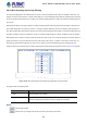
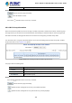
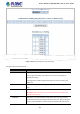
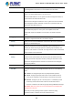
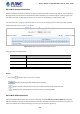
Table Of Contents
- 1. INTRODUCTION
- 2. INSTALLATION
- 3. SWITCH MANAGEMENT
- 4. WEB CONFIGURATION
- 4.1 Main Web Page
- 4.2 System
- 4.2.1 System Information
- 4.2.2 IP Configuration
- 4.2.3 IP Status
- 4.2.4 Users Configuration
- 4.2.5 Privilege Levels
- 4.2.6 NTP Configuration
- 4.2.7 Time Configuration
- 4.2.8 UPnP
- 4.2.9 DHCP Relay
- 4.2.10 DHCP Relay Statistics
- 4.2.11 CPU Load
- 4.2.12 System Log
- 4.2.13 Detailed Log
- 4.2.14 Remote Syslog
- 4.2.15 SMTP Configuration
- 4.2.16 Web Firmware Upgrade
- 4.2.17 TFTP Firmware Upgrade
- 4.2.18 Save Startup Config
- 4.2.19 Configuration Download
- 4.2.20 Configuration Upload
- 4.2.21 Configure Activate
- 4.2.22 Configure Delete
- 4.2.23 Image Select
- 4.2.24 Factory Default
- 4.2.25 System Reboot
- 4.3 Simple Network Management Protocol
- 4.4 Port Management
- 4.5 Link Aggregation
- 4.6 VLAN
- 4.7 Spanning Tree Protocol
- 4.8 Multicast
- 4.8.1 IGMP Snooping
- 4.8.2 Profile Table
- 4.8.3 Address Entry
- 4.8.4 IGMP Snooping Configuration
- 4.8.5 IGMP Snooping VLAN Configuration
- 4.8.6 IGMP Snooping Port Group Filtering
- 4.8.7 IGMP Snooping Status
- 4.8.8 IGMP Group Information
- 4.8.9 IGMPv3 Information
- 4.8.10 MLD Snooping Configuration
- 4.8.11 MLD Snooping VLAN Configuration
- 4.8.12 MLD Snooping Port Group Filtering
- 4.8.13 MLD Snooping Status
- 4.8.14 MLD Group Information
- 4.8.15 MLDv2 Information
- 4.8.16 MVR (Multicast VLAN Registration)
- 4.8.17 MVR Status
- 4.8.18 MVR Groups Information
- 4.8.19 MVR SFM Information
- 4.9 Quality of Service
- 4.9.1 Understanding QoS
- 4.9.2 Port Policing
- 4.9.3 Port Classification
- 4.9.4 Port Scheduler
- 4.9.5 Port Shaping
- 4.9.6 Port Tag Remarking
- 4.9.7 Port DSCP
- 4.9.8 DSCP-based QoS
- 4.9.9 DSCP Translation
- 4.9.10 DSCP Classification
- 4.9.11 QoS Control List
- 4.9.12 QCL Status
- 4.9.13 Storm Control Configuration
- 4.9.14 WRED
- 4.9.15 QoS Statistics
- 4.9.16 Voice VLAN Configuration
- 4.9.17 Voice VLAN OUI Table
- 4.10 Access Control Lists
- 4.11 Authentication
- 4.11.1 Understanding IEEE 802.1X Port-based Authentication
- 4.11.2 Authentication Configuration
- 4.11.3 Network Access Server Configuration
- 4.11.4 Network Access Overview
- 4.11.5 Network Access Statistics
- 4.11.6 RADIUS
- 4.11.7 TACACS+
- 4.11.8 RADIUS Overview
- 4.11.9 RADIUS Details
- 4.11.10 Windows Platform RADIUS Server Configuration
- 4.11.11 802.1X Client Configuration
- 4.12 Security
- 4.12.1 Port Limit Control
- 4.12.2 Access Management
- 4.12.3 Access Management Statistics
- 4.12.4 HTTPs
- 4.12.5 SSH
- 4.12.6 Port Security Status
- 4.12.7 Port Security Detail
- 4.12.8 DHCP Snooping
- 4.12.9 Snooping Table
- 4.12.10 IP Source Guard Configuration
- 4.12.11 IP Source Guard Static Table
- 4.12.12 ARP Inspection
- 4.12.13 ARP Inspection Static Table
- 4.12.14 Dynamic ARP Inspection Table
- 4.13 Address Table
- 4.14 LLDP
- 4.15 Network Diagnostics
- 4.16 Power over Ethernet
- 4.17 Loop Protection
- 4.18 RMON
- 4.19 ONVIF
- 5. SWITCH OPERATION
- 6. TROUBLESHOOTING
- APPENDIX A: Networking Connection
- APPENDIX B : GLOSSARY

User’s Manual of GS-5220 Ultra PoE & PoE+ Series
198
given, it should contain at least one alphabet. MVR VLAN name can be edited for
the existing MVR VLAN entries or it can be added to the new entries.
• IGMP Address
Define the IPv4 address as source address used in IP header for IGMP control
frames. The default IGMP address is not set (0.0.0.0).
When the IGMP address is not set, system uses IPv4 management address of
the IP interface associated with this VLAN.
When the IPv4 management address is not set, system uses the first available
IPv4 management address. Otherwise, system uses a pre-defined value. By
default, this value will be 192.0.2.1.
• Mode
Specify the MVR mode of operation. In Dynamic mode, MVR allows dynamic
MVR membership reports on source ports. In Compatible mode, MVR
membership reports are forbidden on source ports. The default is Dynamic
mode.
• Tagging
Specify whether the traversed IGMP/MLD control frames will be sent as
Untagged or Tagged with MVR VID. The default is Tagged.
• Priority
Specify how the traversed IGMP/MLD control frames will be sent in prioritized
manner. The default Priority is 0.
• LLQI
Define the maximum time to wait for IGMP/MLD report memberships on a
receiver port before removing the port from multicast group membership. The
value is in units of tenths of a seconds. The range is from 0 to 31744. The default
LLQI is 5 tenths or one-half second.
• Interface Channel
Setting
When the MVR VLAN is created, select the IPMC Profile as the channel filtering
condition for the specific MVR VLAN. Summary about the Interface Channel
Profiling (of the MVR VLAN) will be shown by clicking the view button. Profile
selected for designated interface channel is not allowed to have overlapped
permit group address.
• Port
The logical port for the settings.
• Port Role
Configure an MVR port of the designated MVR VLAN as one of the following
roles.
Inactive: The designated port does not participate MVR operations.
Source: Configure uplink ports that receive and send multicast data as
source ports. Subscribers cannot be directly connected to source ports.
Receiver: Configure a port as a receiver port if it is a subscriber port and
should only receive multicast data. It does not receive data unless it
becomes a member of the multicast group by issuing IGMP/MLD messages.
Be Caution: MVR source ports are not recommended to be overlapped with
management VLAN ports.
Select the port role by clicking the Role symbol to switch the setting.
I indicates Inactive; S indicates Source; R indicates Receiver