
GS-5220-Series User Manual
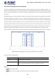
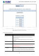
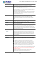
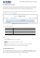
Table Of Contents
- 1. INTRODUCTION
- 2. INSTALLATION
- 3. SWITCH MANAGEMENT
- 4. WEB CONFIGURATION
- 4.1 Main Web Page
- 4.2 System
- 4.2.1 System Information
- 4.2.2 IP Configuration
- 4.2.3 IP Status
- 4.2.4 Users Configuration
- 4.2.5 Privilege Levels
- 4.2.6 NTP Configuration
- 4.2.7 Time Configuration
- 4.2.8 UPnP
- 4.2.9 DHCP Relay
- 4.2.10 DHCP Relay Statistics
- 4.2.11 CPU Load
- 4.2.12 System Log
- 4.2.13 Detailed Log
- 4.2.14 Remote Syslog
- 4.2.15 SMTP Configuration
- 4.2.16 Web Firmware Upgrade
- 4.2.17 TFTP Firmware Upgrade
- 4.2.18 Save Startup Config
- 4.2.19 Configuration Download
- 4.2.20 Configuration Upload
- 4.2.21 Configure Activate
- 4.2.22 Configure Delete
- 4.2.23 Image Select
- 4.2.24 Factory Default
- 4.2.25 System Reboot
- 4.3 Simple Network Management Protocol
- 4.4 Port Management
- 4.5 Link Aggregation
- 4.6 VLAN
- 4.7 Spanning Tree Protocol
- 4.8 Multicast
- 4.8.1 IGMP Snooping
- 4.8.2 Profile Table
- 4.8.3 Address Entry
- 4.8.4 IGMP Snooping Configuration
- 4.8.5 IGMP Snooping VLAN Configuration
- 4.8.6 IGMP Snooping Port Group Filtering
- 4.8.7 IGMP Snooping Status
- 4.8.8 IGMP Group Information
- 4.8.9 IGMPv3 Information
- 4.8.10 MLD Snooping Configuration
- 4.8.11 MLD Snooping VLAN Configuration
- 4.8.12 MLD Snooping Port Group Filtering
- 4.8.13 MLD Snooping Status
- 4.8.14 MLD Group Information
- 4.8.15 MLDv2 Information
- 4.8.16 MVR (Multicast VLAN Registration)
- 4.8.17 MVR Status
- 4.8.18 MVR Groups Information
- 4.8.19 MVR SFM Information
- 4.9 Quality of Service
- 4.9.1 Understanding QoS
- 4.9.2 Port Policing
- 4.9.3 Port Classification
- 4.9.4 Port Scheduler
- 4.9.5 Port Shaping
- 4.9.6 Port Tag Remarking
- 4.9.7 Port DSCP
- 4.9.8 DSCP-based QoS
- 4.9.9 DSCP Translation
- 4.9.10 DSCP Classification
- 4.9.11 QoS Control List
- 4.9.12 QCL Status
- 4.9.13 Storm Control Configuration
- 4.9.14 WRED
- 4.9.15 QoS Statistics
- 4.9.16 Voice VLAN Configuration
- 4.9.17 Voice VLAN OUI Table
- 4.10 Access Control Lists
- 4.11 Authentication
- 4.11.1 Understanding IEEE 802.1X Port-based Authentication
- 4.11.2 Authentication Configuration
- 4.11.3 Network Access Server Configuration
- 4.11.4 Network Access Overview
- 4.11.5 Network Access Statistics
- 4.11.6 RADIUS
- 4.11.7 TACACS+
- 4.11.8 RADIUS Overview
- 4.11.9 RADIUS Details
- 4.11.10 Windows Platform RADIUS Server Configuration
- 4.11.11 802.1X Client Configuration
- 4.12 Security
- 4.12.1 Port Limit Control
- 4.12.2 Access Management
- 4.12.3 Access Management Statistics
- 4.12.4 HTTPs
- 4.12.5 SSH
- 4.12.6 Port Security Status
- 4.12.7 Port Security Detail
- 4.12.8 DHCP Snooping
- 4.12.9 Snooping Table
- 4.12.10 IP Source Guard Configuration
- 4.12.11 IP Source Guard Static Table
- 4.12.12 ARP Inspection
- 4.12.13 ARP Inspection Static Table
- 4.12.14 Dynamic ARP Inspection Table
- 4.13 Address Table
- 4.14 LLDP
- 4.15 Network Diagnostics
- 4.16 Power over Ethernet
- 4.17 Loop Protection
- 4.18 RMON
- 4.19 ONVIF
- 5. SWITCH OPERATION
- 6. TROUBLESHOOTING
- APPENDIX A: Networking Connection
- APPENDIX B : GLOSSARY

User’s Manual of GS-5220 Ultra PoE & PoE+ Series
195
4.8.15 MLDv2 Information
Entries in the MLD SFM Information Table are shown on this page. The MLD SFM (Source-Filtered Multicast) Information Table
also contains the SSM (Source-Specific Multicast) information. This table is sorted first by VLAN ID, then by group, and then by
Port. Different source addresses belong to the same group are treated as single entry. Each page shows up to 99 entries from
the MLD SFM Information table, default being 20, selected through the "entries per page" input field. When first visited, the web
Page will show the first 20 entries from the beginning of the MLD SFM Information Table.
The "Start from VLAN", and "group" input fields allow the user to select the starting point in the MLD SFM Information Table.
The MLDv2 Information screen in Figure 4-8-18 appears.
Figure 4-8-18: MLD SSM Information Page Screenshot
The page includes the following fields:
Object Description
• VLAN ID
VLAN ID of the group.
• Group
Group address of the group displayed.
• Port
Switch port number.
• Mode
Indicates the filtering mode maintained per (VLAN ID, port number, Group
Address) basis. It can be either Include or Exclude.
• Source Address
IP Address of the source. Currently, system limits the total number of IP source
addresses for filtering to be 128.
• Type
Indicates the Type. It can be either Allow or Deny.
• Hardware Filter/Switch
Indicates whether data plane destined to the specific group address from the
source IPv6 address could be handled by chip or not.
Buttons
Auto-refresh : Automatic refresh occurs every 3 seconds.
: Refreshes the displayed table starting from the input fields.
: Updates the table starting from the first entry in the MLD SFM Information Table.
: Updates the table, starting with the entry after the last entry currently displayed.