
GS-5220-Series User Manual
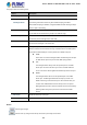
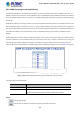
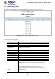
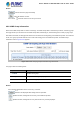
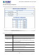
Table Of Contents
- 1. INTRODUCTION
- 2. INSTALLATION
- 3. SWITCH MANAGEMENT
- 4. WEB CONFIGURATION
- 4.1 Main Web Page
- 4.2 System
- 4.2.1 System Information
- 4.2.2 IP Configuration
- 4.2.3 IP Status
- 4.2.4 Users Configuration
- 4.2.5 Privilege Levels
- 4.2.6 NTP Configuration
- 4.2.7 Time Configuration
- 4.2.8 UPnP
- 4.2.9 DHCP Relay
- 4.2.10 DHCP Relay Statistics
- 4.2.11 CPU Load
- 4.2.12 System Log
- 4.2.13 Detailed Log
- 4.2.14 Remote Syslog
- 4.2.15 SMTP Configuration
- 4.2.16 Web Firmware Upgrade
- 4.2.17 TFTP Firmware Upgrade
- 4.2.18 Save Startup Config
- 4.2.19 Configuration Download
- 4.2.20 Configuration Upload
- 4.2.21 Configure Activate
- 4.2.22 Configure Delete
- 4.2.23 Image Select
- 4.2.24 Factory Default
- 4.2.25 System Reboot
- 4.3 Simple Network Management Protocol
- 4.4 Port Management
- 4.5 Link Aggregation
- 4.6 VLAN
- 4.7 Spanning Tree Protocol
- 4.8 Multicast
- 4.8.1 IGMP Snooping
- 4.8.2 Profile Table
- 4.8.3 Address Entry
- 4.8.4 IGMP Snooping Configuration
- 4.8.5 IGMP Snooping VLAN Configuration
- 4.8.6 IGMP Snooping Port Group Filtering
- 4.8.7 IGMP Snooping Status
- 4.8.8 IGMP Group Information
- 4.8.9 IGMPv3 Information
- 4.8.10 MLD Snooping Configuration
- 4.8.11 MLD Snooping VLAN Configuration
- 4.8.12 MLD Snooping Port Group Filtering
- 4.8.13 MLD Snooping Status
- 4.8.14 MLD Group Information
- 4.8.15 MLDv2 Information
- 4.8.16 MVR (Multicast VLAN Registration)
- 4.8.17 MVR Status
- 4.8.18 MVR Groups Information
- 4.8.19 MVR SFM Information
- 4.9 Quality of Service
- 4.9.1 Understanding QoS
- 4.9.2 Port Policing
- 4.9.3 Port Classification
- 4.9.4 Port Scheduler
- 4.9.5 Port Shaping
- 4.9.6 Port Tag Remarking
- 4.9.7 Port DSCP
- 4.9.8 DSCP-based QoS
- 4.9.9 DSCP Translation
- 4.9.10 DSCP Classification
- 4.9.11 QoS Control List
- 4.9.12 QCL Status
- 4.9.13 Storm Control Configuration
- 4.9.14 WRED
- 4.9.15 QoS Statistics
- 4.9.16 Voice VLAN Configuration
- 4.9.17 Voice VLAN OUI Table
- 4.10 Access Control Lists
- 4.11 Authentication
- 4.11.1 Understanding IEEE 802.1X Port-based Authentication
- 4.11.2 Authentication Configuration
- 4.11.3 Network Access Server Configuration
- 4.11.4 Network Access Overview
- 4.11.5 Network Access Statistics
- 4.11.6 RADIUS
- 4.11.7 TACACS+
- 4.11.8 RADIUS Overview
- 4.11.9 RADIUS Details
- 4.11.10 Windows Platform RADIUS Server Configuration
- 4.11.11 802.1X Client Configuration
- 4.12 Security
- 4.12.1 Port Limit Control
- 4.12.2 Access Management
- 4.12.3 Access Management Statistics
- 4.12.4 HTTPs
- 4.12.5 SSH
- 4.12.6 Port Security Status
- 4.12.7 Port Security Detail
- 4.12.8 DHCP Snooping
- 4.12.9 Snooping Table
- 4.12.10 IP Source Guard Configuration
- 4.12.11 IP Source Guard Static Table
- 4.12.12 ARP Inspection
- 4.12.13 ARP Inspection Static Table
- 4.12.14 Dynamic ARP Inspection Table
- 4.13 Address Table
- 4.14 LLDP
- 4.15 Network Diagnostics
- 4.16 Power over Ethernet
- 4.17 Loop Protection
- 4.18 RMON
- 4.19 ONVIF
- 5. SWITCH OPERATION
- 6. TROUBLESHOOTING
- APPENDIX A: Networking Connection
- APPENDIX B : GLOSSARY

User’s Manual of GS-5220 Ultra PoE & PoE+ Series
183
4.8.5 IGMP Snooping VLAN Configuration
Each page shows up to 99 entries from the VLAN table, default being 20, selected through the "entries per page" input field.
When first visited, the web page will show the first 20 entries from the beginning of the VLAN Table. The first displayed will be
the one with the lowest VLAN ID found in the VLAN Table.
The "VLAN" input fields allow the user to select the starting point in the VLAN Table. The IGMP Snooping VLAN Configuration
screen in Figure 4-8-8 appears.
Figure 4-8-8: IGMP Snooping VLAN Configuration Page Screenshot
The page includes the following fields:
Object Description
• Delete
Check to delete the entry. The designated entry will be deleted during the next
save.
• VLAN ID
The VLAN ID of the entry.
• IGMP Snooping Enable
Enable the per-VLAN IGMP Snooping. Only up to 32 VLANs can be selected.
• Querier Election
Enable the IGMP Querier election in the VLAN. Disable to act as an IGMP
Non-Querier.
• Querier Address
Define the IPv4 address as source address used in IP header for IGMP Querier
election.
■ When the Querier address is not set, system uses IPv4 management
address of the IP interface associated with this VLAN.
■ When the IPv4 management address is not set, system uses the first
available IPv4 management address. Otherwise, system uses a
pre-defined value.
By default, this value will be 192.0.2.1
• Compatibility
Compatibility is maintained by hosts and routers taking appropriate actions
depending on the versions of IGMP operating on hosts and routers within a
network. The allowed selection is IGMP-Auto, Forced IGMPv1, Forced
IGMPv2, Forced IGMPv3.
Default compatibility value is IGMP-Auto.