
GS-5220-Series User Manual
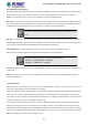
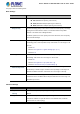
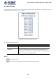
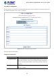
Table Of Contents
- 1. INTRODUCTION
- 2. INSTALLATION
- 3. SWITCH MANAGEMENT
- 4. WEB CONFIGURATION
- 4.1 Main Web Page
- 4.2 System
- 4.2.1 System Information
- 4.2.2 IP Configuration
- 4.2.3 IP Status
- 4.2.4 Users Configuration
- 4.2.5 Privilege Levels
- 4.2.6 NTP Configuration
- 4.2.7 Time Configuration
- 4.2.8 UPnP
- 4.2.9 DHCP Relay
- 4.2.10 DHCP Relay Statistics
- 4.2.11 CPU Load
- 4.2.12 System Log
- 4.2.13 Detailed Log
- 4.2.14 Remote Syslog
- 4.2.15 SMTP Configuration
- 4.2.16 Web Firmware Upgrade
- 4.2.17 TFTP Firmware Upgrade
- 4.2.18 Save Startup Config
- 4.2.19 Configuration Download
- 4.2.20 Configuration Upload
- 4.2.21 Configure Activate
- 4.2.22 Configure Delete
- 4.2.23 Image Select
- 4.2.24 Factory Default
- 4.2.25 System Reboot
- 4.3 Simple Network Management Protocol
- 4.4 Port Management
- 4.5 Link Aggregation
- 4.6 VLAN
- 4.7 Spanning Tree Protocol
- 4.8 Multicast
- 4.8.1 IGMP Snooping
- 4.8.2 Profile Table
- 4.8.3 Address Entry
- 4.8.4 IGMP Snooping Configuration
- 4.8.5 IGMP Snooping VLAN Configuration
- 4.8.6 IGMP Snooping Port Group Filtering
- 4.8.7 IGMP Snooping Status
- 4.8.8 IGMP Group Information
- 4.8.9 IGMPv3 Information
- 4.8.10 MLD Snooping Configuration
- 4.8.11 MLD Snooping VLAN Configuration
- 4.8.12 MLD Snooping Port Group Filtering
- 4.8.13 MLD Snooping Status
- 4.8.14 MLD Group Information
- 4.8.15 MLDv2 Information
- 4.8.16 MVR (Multicast VLAN Registration)
- 4.8.17 MVR Status
- 4.8.18 MVR Groups Information
- 4.8.19 MVR SFM Information
- 4.9 Quality of Service
- 4.9.1 Understanding QoS
- 4.9.2 Port Policing
- 4.9.3 Port Classification
- 4.9.4 Port Scheduler
- 4.9.5 Port Shaping
- 4.9.6 Port Tag Remarking
- 4.9.7 Port DSCP
- 4.9.8 DSCP-based QoS
- 4.9.9 DSCP Translation
- 4.9.10 DSCP Classification
- 4.9.11 QoS Control List
- 4.9.12 QCL Status
- 4.9.13 Storm Control Configuration
- 4.9.14 WRED
- 4.9.15 QoS Statistics
- 4.9.16 Voice VLAN Configuration
- 4.9.17 Voice VLAN OUI Table
- 4.10 Access Control Lists
- 4.11 Authentication
- 4.11.1 Understanding IEEE 802.1X Port-based Authentication
- 4.11.2 Authentication Configuration
- 4.11.3 Network Access Server Configuration
- 4.11.4 Network Access Overview
- 4.11.5 Network Access Statistics
- 4.11.6 RADIUS
- 4.11.7 TACACS+
- 4.11.8 RADIUS Overview
- 4.11.9 RADIUS Details
- 4.11.10 Windows Platform RADIUS Server Configuration
- 4.11.11 802.1X Client Configuration
- 4.12 Security
- 4.12.1 Port Limit Control
- 4.12.2 Access Management
- 4.12.3 Access Management Statistics
- 4.12.4 HTTPs
- 4.12.5 SSH
- 4.12.6 Port Security Status
- 4.12.7 Port Security Detail
- 4.12.8 DHCP Snooping
- 4.12.9 Snooping Table
- 4.12.10 IP Source Guard Configuration
- 4.12.11 IP Source Guard Static Table
- 4.12.12 ARP Inspection
- 4.12.13 ARP Inspection Static Table
- 4.12.14 Dynamic ARP Inspection Table
- 4.13 Address Table
- 4.14 LLDP
- 4.15 Network Diagnostics
- 4.16 Power over Ethernet
- 4.17 Loop Protection
- 4.18 RMON
- 4.19 ONVIF
- 5. SWITCH OPERATION
- 6. TROUBLESHOOTING
- APPENDIX A: Networking Connection
- APPENDIX B : GLOSSARY

User’s Manual of GS-5220 Ultra PoE & PoE+ Series
167
• Path Cost
Controls the path cost incurred by the port. The Auto setting will set the path cost
as appropriate by the physical link speed, using the 802.1D recommended
values. Using the Specific setting, a user-defined value can be entered. The
path cost is used when establishing the active topology of the network. Lower
path cost ports are chosen as forwarding ports in favor of higher path cost ports.
Valid values are in the range 1 to 200000000.
• Priority
Controls the port priority. This can be used to control priority of ports having
identical port cost. (See above).
Default: 128
Range: 0-240, in steps of 16
• AdminEdge
Controls whether the operEdge flag should start as being set or cleared. (The
initial operEdge state when a port is initialized).
• AutoEdge
Controls whether the bridge should enable automatic edge detection on the
bridge port. This allows operEdge to be derived from whether BPDU's are
received on the port or not.
• Restricted Role
If enabled, causes the port not to be selected as Root Port for the CIST or any
MSTI, even if it has the best spanning tree priority vector. Such a port will be
selected as an Alternate Port after the Root Port has been selected. If set, it can
cause lack of spanning tree connectivity. It can be set by a network administrator
to prevent bridges external to a core region of the network influence the spanning
tree active topology, possibly because those bridges are not under the full control
of the administrator. This feature is also known as Root Guard.
• Restricted TCN
If enabled, causes the port not to propagate received topology change
notifications and topology changes to other ports. If set it can cause temporary
loss of connectivity after changes in a spanning tree's active topology as a result
of persistently incorrect learned station location information. It is set by a network
administrator to prevent bridges external to a core region of the network, causing
address flushing in that region, possibly because those bridges are not under the
full control of the administrator or the physical link state of the attached LANs
transits frequently.
• BPDU Guard
If enabled, causes the port to disable itself upon receiving valid BPDU's. Contrary
to the similar bridge setting, the port Edge status does not effect this setting.
A port entering error-disabled state due to this setting is subject to the bridge Port
Error Recovery setting as well.
• Point-to-point
Controls whether the port connects to a point-to-point LAN rather than a shared
medium. This can be automatically determined, or forced either true or false.
Transitions to the forwarding state is faster for point-to-point LANs than for
shared media.