
GS-5220-Series User Manual
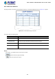
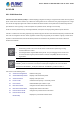
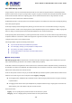
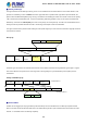
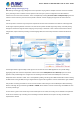
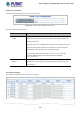
Table Of Contents
- 1. INTRODUCTION
- 2. INSTALLATION
- 3. SWITCH MANAGEMENT
- 4. WEB CONFIGURATION
- 4.1 Main Web Page
- 4.2 System
- 4.2.1 System Information
- 4.2.2 IP Configuration
- 4.2.3 IP Status
- 4.2.4 Users Configuration
- 4.2.5 Privilege Levels
- 4.2.6 NTP Configuration
- 4.2.7 Time Configuration
- 4.2.8 UPnP
- 4.2.9 DHCP Relay
- 4.2.10 DHCP Relay Statistics
- 4.2.11 CPU Load
- 4.2.12 System Log
- 4.2.13 Detailed Log
- 4.2.14 Remote Syslog
- 4.2.15 SMTP Configuration
- 4.2.16 Web Firmware Upgrade
- 4.2.17 TFTP Firmware Upgrade
- 4.2.18 Save Startup Config
- 4.2.19 Configuration Download
- 4.2.20 Configuration Upload
- 4.2.21 Configure Activate
- 4.2.22 Configure Delete
- 4.2.23 Image Select
- 4.2.24 Factory Default
- 4.2.25 System Reboot
- 4.3 Simple Network Management Protocol
- 4.4 Port Management
- 4.5 Link Aggregation
- 4.6 VLAN
- 4.7 Spanning Tree Protocol
- 4.8 Multicast
- 4.8.1 IGMP Snooping
- 4.8.2 Profile Table
- 4.8.3 Address Entry
- 4.8.4 IGMP Snooping Configuration
- 4.8.5 IGMP Snooping VLAN Configuration
- 4.8.6 IGMP Snooping Port Group Filtering
- 4.8.7 IGMP Snooping Status
- 4.8.8 IGMP Group Information
- 4.8.9 IGMPv3 Information
- 4.8.10 MLD Snooping Configuration
- 4.8.11 MLD Snooping VLAN Configuration
- 4.8.12 MLD Snooping Port Group Filtering
- 4.8.13 MLD Snooping Status
- 4.8.14 MLD Group Information
- 4.8.15 MLDv2 Information
- 4.8.16 MVR (Multicast VLAN Registration)
- 4.8.17 MVR Status
- 4.8.18 MVR Groups Information
- 4.8.19 MVR SFM Information
- 4.9 Quality of Service
- 4.9.1 Understanding QoS
- 4.9.2 Port Policing
- 4.9.3 Port Classification
- 4.9.4 Port Scheduler
- 4.9.5 Port Shaping
- 4.9.6 Port Tag Remarking
- 4.9.7 Port DSCP
- 4.9.8 DSCP-based QoS
- 4.9.9 DSCP Translation
- 4.9.10 DSCP Classification
- 4.9.11 QoS Control List
- 4.9.12 QCL Status
- 4.9.13 Storm Control Configuration
- 4.9.14 WRED
- 4.9.15 QoS Statistics
- 4.9.16 Voice VLAN Configuration
- 4.9.17 Voice VLAN OUI Table
- 4.10 Access Control Lists
- 4.11 Authentication
- 4.11.1 Understanding IEEE 802.1X Port-based Authentication
- 4.11.2 Authentication Configuration
- 4.11.3 Network Access Server Configuration
- 4.11.4 Network Access Overview
- 4.11.5 Network Access Statistics
- 4.11.6 RADIUS
- 4.11.7 TACACS+
- 4.11.8 RADIUS Overview
- 4.11.9 RADIUS Details
- 4.11.10 Windows Platform RADIUS Server Configuration
- 4.11.11 802.1X Client Configuration
- 4.12 Security
- 4.12.1 Port Limit Control
- 4.12.2 Access Management
- 4.12.3 Access Management Statistics
- 4.12.4 HTTPs
- 4.12.5 SSH
- 4.12.6 Port Security Status
- 4.12.7 Port Security Detail
- 4.12.8 DHCP Snooping
- 4.12.9 Snooping Table
- 4.12.10 IP Source Guard Configuration
- 4.12.11 IP Source Guard Static Table
- 4.12.12 ARP Inspection
- 4.12.13 ARP Inspection Static Table
- 4.12.14 Dynamic ARP Inspection Table
- 4.13 Address Table
- 4.14 LLDP
- 4.15 Network Diagnostics
- 4.16 Power over Ethernet
- 4.17 Loop Protection
- 4.18 RMON
- 4.19 ONVIF
- 5. SWITCH OPERATION
- 6. TROUBLESHOOTING
- APPENDIX A: Networking Connection
- APPENDIX B : GLOSSARY

User’s Manual of GS-5220 Ultra PoE & PoE+ Series
136
■ Port Overlapping
Port overlapping can be used to allow access to commonly shared network resources among different VLAN groups, such as
file servers or printers. Note that if you implement VLANs which do not overlap, but still need to communicate, you can connect
them by enabled routing on this switch.
■ Untagged VLANs
Untagged (or static) VLANs are typically used to reduce broadcast traffic and to increase security. A group of network users
assigned to a VLAN form a broadcast domain that is separate from other VLANs configured on the switch. Packets are
forwarded only between ports that are designated for the same VLAN. Untagged VLANs can be used to manually isolate user
groups or subnets.
4.6.3 VLAN Port Configuration
This page is used for configuring the Managed Switch port VLAN. The VLAN per Port Configuration page contains fields for
managing ports that are part of a VLAN. The port default VLAN ID (PVID) is configured on the VLAN Port Configuration page. All
untagged packets arriving to the device are tagged by the ports PVID.
Understand nomenclature of the Switch
■ IEEE 802.1Q Tagged and Untagged
Every port on an 802.1Q compliant switch can be configured as tagged or untagged.
• Tagged:
Ports with tagging enabled will put the VID number, priority and other VLAN information into the
header of all packets that flow into
those ports. If a packet has previously been tagged, the port
will not alter the packet, thus keeping the VLAN information intact. The VLAN information in the
tag can then be used by other 802.1Q compliant devices on the network to make
packet-forwarding decisions.
• Untagged:
Ports with untagging enabled will strip the 802.1Q tag from all packets that flow into those
ports. If the packet doesn't have an 802.1Q VLAN tag, the port will not alter the packet. Thus,
all packets received by and forwarded by an untagging port will have no 802.1Q VLAN
information. (Remember that the PVID is only used internally within the Switch). Untagging is
used to send packets from an 802.1Q-compliant network device to a non-compliant network
device.
Frame Income
Frame Leave
Income Frame is tagged Income Frame is untagged
Leave port is tagged Frame remains tagged Tag is inserted
Leave port is untagged Tag is removed Frame remain untagged
Table 4-6-1: Ingress / Egress Port with VLAN VID Tag / Untag Table