
GS-5220-Series User Manual

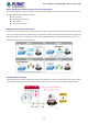
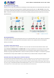
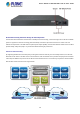
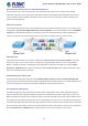


Table Of Contents
- 1. INTRODUCTION
- 2. INSTALLATION
- 3. SWITCH MANAGEMENT
- 4. WEB CONFIGURATION
- 4.1 Main Web Page
- 4.2 System
- 4.2.1 System Information
- 4.2.2 IP Configuration
- 4.2.3 IP Status
- 4.2.4 Users Configuration
- 4.2.5 Privilege Levels
- 4.2.6 NTP Configuration
- 4.2.7 Time Configuration
- 4.2.8 UPnP
- 4.2.9 DHCP Relay
- 4.2.10 DHCP Relay Statistics
- 4.2.11 CPU Load
- 4.2.12 System Log
- 4.2.13 Detailed Log
- 4.2.14 Remote Syslog
- 4.2.15 SMTP Configuration
- 4.2.16 Web Firmware Upgrade
- 4.2.17 TFTP Firmware Upgrade
- 4.2.18 Save Startup Config
- 4.2.19 Configuration Download
- 4.2.20 Configuration Upload
- 4.2.21 Configure Activate
- 4.2.22 Configure Delete
- 4.2.23 Image Select
- 4.2.24 Factory Default
- 4.2.25 System Reboot
- 4.3 Simple Network Management Protocol
- 4.4 Port Management
- 4.5 Link Aggregation
- 4.6 VLAN
- 4.7 Spanning Tree Protocol
- 4.8 Multicast
- 4.8.1 IGMP Snooping
- 4.8.2 Profile Table
- 4.8.3 Address Entry
- 4.8.4 IGMP Snooping Configuration
- 4.8.5 IGMP Snooping VLAN Configuration
- 4.8.6 IGMP Snooping Port Group Filtering
- 4.8.7 IGMP Snooping Status
- 4.8.8 IGMP Group Information
- 4.8.9 IGMPv3 Information
- 4.8.10 MLD Snooping Configuration
- 4.8.11 MLD Snooping VLAN Configuration
- 4.8.12 MLD Snooping Port Group Filtering
- 4.8.13 MLD Snooping Status
- 4.8.14 MLD Group Information
- 4.8.15 MLDv2 Information
- 4.8.16 MVR (Multicast VLAN Registration)
- 4.8.17 MVR Status
- 4.8.18 MVR Groups Information
- 4.8.19 MVR SFM Information
- 4.9 Quality of Service
- 4.9.1 Understanding QoS
- 4.9.2 Port Policing
- 4.9.3 Port Classification
- 4.9.4 Port Scheduler
- 4.9.5 Port Shaping
- 4.9.6 Port Tag Remarking
- 4.9.7 Port DSCP
- 4.9.8 DSCP-based QoS
- 4.9.9 DSCP Translation
- 4.9.10 DSCP Classification
- 4.9.11 QoS Control List
- 4.9.12 QCL Status
- 4.9.13 Storm Control Configuration
- 4.9.14 WRED
- 4.9.15 QoS Statistics
- 4.9.16 Voice VLAN Configuration
- 4.9.17 Voice VLAN OUI Table
- 4.10 Access Control Lists
- 4.11 Authentication
- 4.11.1 Understanding IEEE 802.1X Port-based Authentication
- 4.11.2 Authentication Configuration
- 4.11.3 Network Access Server Configuration
- 4.11.4 Network Access Overview
- 4.11.5 Network Access Statistics
- 4.11.6 RADIUS
- 4.11.7 TACACS+
- 4.11.8 RADIUS Overview
- 4.11.9 RADIUS Details
- 4.11.10 Windows Platform RADIUS Server Configuration
- 4.11.11 802.1X Client Configuration
- 4.12 Security
- 4.12.1 Port Limit Control
- 4.12.2 Access Management
- 4.12.3 Access Management Statistics
- 4.12.4 HTTPs
- 4.12.5 SSH
- 4.12.6 Port Security Status
- 4.12.7 Port Security Detail
- 4.12.8 DHCP Snooping
- 4.12.9 Snooping Table
- 4.12.10 IP Source Guard Configuration
- 4.12.11 IP Source Guard Static Table
- 4.12.12 ARP Inspection
- 4.12.13 ARP Inspection Static Table
- 4.12.14 Dynamic ARP Inspection Table
- 4.13 Address Table
- 4.14 LLDP
- 4.15 Network Diagnostics
- 4.16 Power over Ethernet
- 4.17 Loop Protection
- 4.18 RMON
- 4.19 ONVIF
- 5. SWITCH OPERATION
- 6. TROUBLESHOOTING
- APPENDIX A: Networking Connection
- APPENDIX B : GLOSSARY

User’s Manual of GS-5220 Ultra PoE & PoE+ Series
12
1.2 Product Description
Amazing Ultra PoE Managed Switch with Advanced L2+/L4 Switching and Security
PLANET GS-5220 Ultra PoE & PoE+ Series is a Cost-optimized, 1U, Gigabit Ultra PoE Managed Switch featuring PLANET
intelligent PoE functions to improve the availability of critical business applications. It provides IPv6/IPv4 dual stack
management and built-in L2+/L4 Gigabit switching engine along with 16/24 10/100/1000BASE-T ports featuring 36/75-watt
PoE, 4 Gigabit TP/SFP combo ports and 2/4 additional 10Gigabit SFP+ ports. With a total power budget of up to 400/600
watts for different kinds of PoE applications, the GS-5220 Ultra PoE & PoE+ Series provides a quick, safe and cost-effective
ultra PoE network solution for small businesses and enterprises.
Convenient and Smart ONVIF Devices with Detection Feature
PLANET has newly developed an awesome feature -- ONVIF Support -- which is specifically designed for co-operating with
Video IP surveillances. From the GS-5220 Ultra PoE & PoE+ Series GUI, clients just need one click to search and show all of
the ONVIF devices via network application. In addition, clients can upload floor images into switch and allows for deploying
location of surveillance devices for easier inspection and planning. Moreover, clients can get real-time surveillance’s information
and online/offline status, and it also allows PoE reboot control from GUI.
75 Watts of Power over 4-pair UTP (For Ultra PoE Switches)
The GS-5220 Ultra PoE Series’ ultra PoE solution adopts the IEEE 802.3at/af standard. Instead of delivering power over 2-pair
twisted UTP – be it end-span (Pins 1,2,3 and 6) or mid-span (Pins 4,5,7 and 8), it provides the capability to source up to 75 watts
of power by using all the four pairs of standard Cat.5e/6 Ethernet cabling. In the new 4-pair system, two PSE controllers will be
used to power both the data pairs and the spare pairs. It can offer more PoE applications, such as:
■ PoE PTZ speed dome
■ Any network device that needs higher PoE power to work normally
■ Thin-client
■ AIO (All-in-One) touch PC
■ Remote digital signage display