L2+ Managed Gigabit / 10 Gigabit Ethernet Switch GS-5220 Series Quick Installation Guide
Table of Contents 1. Package Contents........................................................................................ 3 2. Requirements.............................................................................................. 4 3. Terminal Setup............................................................................................ 5 4. Logon to Console......................................................................................... 6 5. Configuring IP Address.......................
1. Package Contents Thank you for purchasing PLANET L2+ Managed Gigabit/10 Gigabit Ethernet Switch.
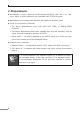
2. Requirements zz Workstations running Windows XP/2003/Vista/7/8/2008, MAC OS X or later, Linux, UNIX, or other platforms are compatible with TCP/IP protocols. zz Workstations are installed with Ethernet NIC (Network Interface Card) zz Serial Port Connection (Terminal) The above Workstations come with COM Port (DB9) or USB-to-RS232 converter. The above Workstations have been installed with terminal emulator, such as Hyper Terminal included in Windows XP/2003.
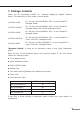
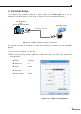
3. Terminal Setup To configure the system, connect a serial cable to a COM port on a PC or notebook computer and to RJ45 type of serial port of the Managed Switch. PC / Workstation with Terminal Emulation Software Managed Switch RS-232 to RJ45 Cable Serial Port RJ45 Console Port Figure 3-1 Managed Switch Console Connectivity A terminal program is required to make the software connection to the Managed Switch. 1. Run terminal program on the OS. 2.
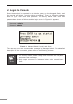
4. Logon to Console Once the terminal is connected to the device, power on the Managed Switch, and the terminal will display “running testing procedures”. Then, the following message asks to log-in user name and password. The factory default user name and password are shown as follows and the login screen in Figure 4-1 appears. Username: admin Password: admin Figure 4-1: Managed Switch Console Login Screen The user can now enter commands to manage the Managed Switch.
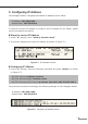
5. Configuring IP Address The Managed Switch is shipped with default IP address shown below. IP Address: 192.168.0.100 Subnet Mask: 255.255.255.0 To check the current IP address or modify a new IP address for the Switch, please use the procedures as follows: Show the current IP Address 1. At the “#” prompt, enter “show ip interface brief”. 2. The screen displays the current IP address as shown in Figure 5-1. Figure 5-1: IP Information Screen Configuring IP Address 3.
4. Repeat step 1 to check if the IP address is changed. Store current switch configuration 5. At the “#” prompt, enter the following command and press # copy running-config startup-config Figure 5-3: Saving Current Configuration Command Screen If the IP is successfully configured, the Managed Switch will apply the new IP address setting immediately. You can access the Web interface of the Managed Switch through the new IP address.
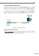
6. Starting Web Management The following shows how to start up the Web Management of the Managed Switch. Note the Managed Switch is configured through an Ethernet connection. Please make sure the manager PC must be set on the same IP subnet address. For example, the default IP address of the Managed Switch is 192.168.0.100, then the manager PC should be set at 192.168.0.x (where x is a number between 1 and 254, except 100), and the default subnet mask is 255.255.255.0. PC / Workstation with Web Browser 192.
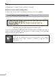
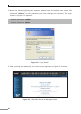
2. When the following dialog box appears, please enter the default user name and password “admin” (or the password you have changed via console). The login screen in Figure 6-2 appears. Default Username: admin Default Password: admin Figure 6-2: Login Screen 3. After entering the password, the main screen appears as Figure 6-3 shows.
The Switch Menu on the left of the Web page let you access all the commands and statistics the Managed Switch provides. Figure 6-4: Switch Menu Note If you are not familiar with Switch functions or the related parameter, press “Help icon” anytime on the Web page to get the help description. Now, you can use the Web management interface to continue the Switch management or manage the Switch by console interface. Please refer to the user’s manual for more.
7. Saving Configuration In the Managed Switch, the running configuration file stores in the RAM. In the current version, the running configuration sequence of running-config can be saved from the RAM to FLASH by executing save startup config command, so that the running configuration sequence becomes the startup configuration file, which is called configuration save.
8. Recovering Back to Default Configuration IP address has been changed or admin password has been forgotten – To reset the IP address to the default IP address “192.168.0.100” or reset the login password to default value, press the hardware reset button on the rear panel for about 10 seconds. After the device is rebooted, you can login the management Web interface within the same subnet of 192.168.0.xx.
2 2 4 6 8 GS-5220-46S2C4X FAN1 2 Console FAN2 SYS PWR 1 Reset 115200, N, 8, 1 1000 ACT 10/100 ACT 1 1 2 3 4 5 6 7 8 Figure 8-3: GS-5220-46S2C4X Reset Button Console 11520,N,8,1 Reset 49 50 10G/1G 10G/1G Figure 8-4: GS-5220-48T4X Reset Button 14
9. Customer Support Thank you for purchasing PLANET products. You can browse our online FAQ resource and User’s Manual on PLANET Web site first to check if it could solve your issue. If you need more support information, please contact PLANET switch support team. PLANET online FAQ: http://www.planet.com.tw/en/support/faq.php?type=1 Switch support team mail address: support_switch@planet.com.tw GS-5220 Series User’s Manual: http://www.planet.com.tw/en/support/download.