User’s Manual of GS-4210 Series Trademarks Copyright © PLANET Technology Corp. 2016. Contents are subject to revision without prior notice. PLANET is a registered trademark of PLANET Technology Corp. All other trademarks belong to their respective owners.
User’s Manual of GS-4210 Series TABLE OF CONTENTS 1. INTRODUCTION.................................................................................................................. 10 1.1 Packet Contents .........................................................................................................................................10 1.2 Product Description ...................................................................................................................................11 1.
User’s Manual of GS-4210 Series 4.2.1 System Information..............................................................................................................................................61 4.2.2 IP Configurations .................................................................................................................................................62 4.2.3 IPv6 Configuration ..................................................................................................................
User’s Manual of GS-4210 Series 4.4.3 LAG Port Setting................................................................................................................................................ 114 4.4.4 LACP Setting ..................................................................................................................................................... 116 4.4.5 LACP Port Setting.................................................................................................................
User’s Manual of GS-4210 Series 4.7.2.7 IGMP Forward All ....................................................................................................................................182 4.7.3 IGMP Snooping Statics......................................................................................................................................183 4.7.4 MLD Snooping........................................................................................................................................
User’s Manual of GS-4210 Series 4.9.1.2 802.1X Setting .........................................................................................................................................225 4.9.1.3 802.1X Port Setting .................................................................................................................................226 4.9.1.4 Guest VLAN Setting ................................................................................................................................
User’s Manual of GS-4210 Series 4.9.11.2 DoS Port Setting ....................................................................................................................................276 4.9.12 Storm Control...................................................................................................................................................277 4.9.12.1 Global Setting ...........................................................................................................................
User’s Manual of GS-4210 Series 4.14.5 RMON History .................................................................................................................................................335 4.14.6 RMON History Log ..........................................................................................................................................336 4.15 Power over Ethernet .......................................................................................................................
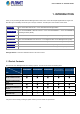
User’s Manual of GS-4210 Series 1. INTRODUCTION Thank you for purchasing PLANET GS-4210 Managed Switch series, which comes with multiple Gigabit Ethernet copper and SFP fiber optic connectibility and robust layer 2 and layer 4 features. The description of this model is shown below: 8-Port 10/100/1000T 802.3at PoE + 2-Port 100/1000X SFP Managed Switch GS-4210-8P2S GS-4210-8P2T2S 8-Port 10/100/1000BASE-T 802.
User’s Manual of GS-4210 Series 1.2 Product Description Perfect Managed PoE+ Switch with Full PoE+ Power Budget PLANET GS-4210 PoE series is the new generation of PLANET Managed Gigabit PoE+ Switch featuring PLANET intelligent PoE functions to improve the availability of critical business applications. It provides a quick, safe and cost-effective Power over Ethernet network solution to IP security surveillance for small businesses and enterprises.
User’s Manual of GS-4210 Series PoE Schedule for Energy Saving Under the trend of energy saving worldwide and contributing to environmental protection, the GS-4210 PoE series can effectively control the power supply besides its capability of giving high watts power. The “PoE schedule” function helps you to enable or disable PoE power feeding for each PoE port during specified time intervals and it is a powerful function to help SMBs or enterprises save power and money.
User’s Manual of GS-4210 Series Robust Layer 2 Features The GS-4210 series can be programmed for advanced switch management functions such as dynamic port link aggregation, 802.1Q VLAN and Q-in-Q VLAN, Multiple Spanning Tree protocol (MSTP), Loop and BPDU Guard, IGMP Snooping, and MLD Snooping. Via the link aggregation, the GS-4210 series allows the operation of a high-speed trunk to combine with multiple ports such as a 16Gbps fat pipe, and supports fail-over as well.
User’s Manual of GS-4210 Series Flexibility and Extension Solution The GS-4210 series provides Gigabit TP/SFP interfaces supporting 10/100/1000BASE-T RJ45 copper to connect with surveillance network devices such as NVR, Video Streaming Server or NAS to facilitate surveillance management. Or through these dual-speed fiber SFP slots, it can also connect with the 100BASE-FX/1000BASE-SX/LX SFP (small form-factor pluggable) fiber transceiver and then to backbone switch and monitoring center over a long distance.
User’s Manual of GS-4210 Series 1.4 Product Features Physical Port ■ 10/100/1000BASE-T Gigabit RJ45 copper ■ 100/1000BASE-X mini-GBIC/SFP slots. ■ RJ45 console interface for switch basic management and setup Power over Ethernet (GS-4210 PoE Series) ■ Complies with IEEE 802.3at high power over Ethernet end-span PSE ■ Complies with IEEE 802.3af power over Ethernet end-span PSE ■ IEEE 802.3af/802.3at devices powered ■ Supports PoE power up to 30.
User’s Manual of GS-4210 Series Maximum 8 trunk groups, up to 8 ports per trunk group ■ Provides port mirror (many-to-1) ■ Loop protection to avoid broadcast loops Quality of Service ■ Ingress/Egress Rate Limit per port bandwidth control ■ Storm Control support Broadcast/Unknown unicast/Unknown multicast ■ Traffic classification - IEEE 802.
User’s Manual of GS-4210 Series Management ■ IPv4 and IPv6 dual stack management ■ Switch Management Interface - Web switch management Telnet Command Line Interface SNMP v1, v2c and v3 SSH/SSL secure access ■ User Privilege Levels Control ■ Built-in Trivial File Transfer Protocol (TFTP) client ■ BOOTP and DHCP for IP address assignment ■ System Maintenance - Firmware upload/download via HTTP / TFTP Configuration upload/download through Web interface Dual Images Hardware reset button for system reboot or
User’s Manual of GS-4210 Series 1.5 Product Specifications GS-4210-8P2S / GS-4210-8P2T2S Product GS-4210-8P2S GS-4210-8P2T2S Hardware Specifications Copper Ports SFP/mini-GBIC Slots PoE Injector Port 8 x 10/100/1000BASE-T RJ45 10 x 10/100/1000BASE-T RJ45 auto-MDI/MDI-X ports auto-MDI/MDI-X ports 2 x 100/1000BASE-X SFP interfaces with 2 x 100/1000BASE-X SFP interfaces Port-9 to Port-10. with Port-11 to Port-12.
User’s Manual of GS-4210 Series 120 watts (max.) @ 25 degrees C 240 watts (max.) @ 25 degrees C 100 watts (max.) @ 50 degrees C 200 watts (max.) @ 50 degrees C PoE Ability PD @ 9 watts 8 units 8 units PoE Ability PD @ 15 watts 8 units 8 units PoE Ability PD @ 30 watts 4 units 8 units PoE Power Budget Layer 2 Functions Port Mirroring TX/RX/both Many-to-1 monitor 802.1Q tagged-based VLAN Up to 256 VLAN groups, out of 4094 VLAN IDs 802.
User’s Manual of GS-4210 Series System log LLDP protocol SNTP Secure Management Interfaces SSH/SSL, SNMP v3 RFC 1213 MIB-II RFC 1215 Generic Traps RFC 1493 Bridge MIB SNMP MIBs RFC 2674 Bridge MIB Extensions RFC 2737 Entity MIB (Version 2) RFC 2819 RMON (1, 2, 3, 9) RFC 2863 Interface Group MIB RFC 3635 Ethernet-like MIB Standards Conformance Regulatory Compliance FCC Part 15 Class A, CE IEEE 802.3 10BASE-T IEEE 802.3u 100BASE-TX/100BASE-FX IEEE 802.3z Gigabit SX/LX IEEE 802.3ab Gigabit 1000T IEEE 802.
User’s Manual of GS-4210 Series GS-4210-16P4C Product GS-4210-16P4C Hardware Specifications Copper Ports SFP/mini-GBIC Slots 20 x 10/100/1000BASE-T RJ45 auto-MDI/MDI-X ports 4 x 100/1000BASE-X SFP interfaces shared with Port-17 to Port-20. Supports 100/1000Mbps dual mode and DDM PoE Injector Port 16 ports with 802.
User’s Manual of GS-4210 Series Many-to-1 monitor 802.1Q tagged-based VLAN Up to 256 VLAN groups, out of 4094 VLAN IDs 802.1ad Q-in-Q tunneling VLAN Voice VLAN Protocol VLAN Private VLAN (Protected port) GVRP Link Aggregation Spanning Tree Protocol IEEE 802.
User’s Manual of GS-4210 Series RFC 2819 RMON (1, 2, 3, 9) RFC 2863 Interface Group MIB RFC 3635 Ethernet-like MIB Standards Conformance Regulatory Compliance FCC Part 15 Class A, CE IEEE 802.3 10BASE-T IEEE 802.3u 100BASE-TX/100BASE-FX IEEE 802.3z Gigabit SX/LX IEEE 802.3ab Gigabit 1000T IEEE 802.3x flow control and back pressure IEEE 802.3ad port trunk with LACP IEEE 802.1D Spanning Tree Protocol IEEE 802.1w Rapid Spanning Tree Protocol IEEE 802.1s Multiple Spanning Tree Protocol IEEE 802.
User’s Manual of GS-4210 Series GS-4210-24P4C / GS-4210-24PL4C Product GS-4210-24P4C GS-4210-24PL4C Hardware Specifications Copper Ports SFP/mini-GBIC Slots 28 x 10/100/1000BASE-T RJ45 auto-MDI/MDI-X ports 4 x 100/1000BASE-X SFP interfaces shared with Port-25 to Port-28. Supports 100/1000Mbps dual mode and DDM PoE Injector Port 24 ports with 802.
User’s Manual of GS-4210 Series Many-to-1 monitor 802.1Q tagged-based VLAN Up to 256 VLAN groups, out of 4094 VLAN IDs 802.1ad Q-in-Q tunneling VLAN Voice VLAN Protocol VLAN Private VLAN (Protected port) GVRP Link Aggregation Spanning Tree Protocol IEEE 802.
User’s Manual of GS-4210 Series RFC 2819 RMON (1, 2, 3, 9) RFC 2863 Interface Group MIB RFC 3635 Ethernet-like MIB Standards Conformance Regulatory Compliance FCC Part 15 Class A, CE IEEE 802.3 10BASE-T IEEE 802.3u 100BASE-TX/100BASE-FX IEEE 802.3z Gigabit SX/LX IEEE 802.3ab Gigabit 1000T IEEE 802.3x flow control and back pressure IEEE 802.3ad port trunk with LACP IEEE 802.1D Spanning Tree Protocol IEEE 802.1w Rapid Spanning Tree Protocol IEEE 802.1s Multiple Spanning Tree Protocol IEEE 802.
User’s Manual of GS-4210 Series GS-4210-48T4S Product GS-4210-48T4S GS-4210-48P4S Hardware Specifications Copper Ports SFP/mini-GBIC Slots 48 x 10/100/1000BASE-T RJ45 auto-MDI/MDI-X ports 4 100/1000BASE-X SFP interfaces, Supports 100/1000Mbps dual mode and DDM PoE Injector Port --- Switch Architecture Store-and-Forward Switch Fabric 104Gbps/non-blocking Switch Throughput@64Bytes 77.
User’s Manual of GS-4210 Series PoE Power Output --- Per port 52V DC, 36 watts (max.) Power Pin Assignment --- 1/2(+), 3/6(-) PoE Power Budget --- PoE Ability PD @ 9 watts --- 48 units PoE Ability PD @ 15 watts --- 29 units PoE Ability PD @ 30 watts --- 14 units 440 watts (max.) @ 25 degrees C 380 watts (max.) @ 50 degrees C Layer 2 Functions Port Mirroring TX/RX/Both Many-to-1 monitor 802.1Q tagged-based VLAN Up to 256 VLAN groups, out of 4094 VLAN IDs 802.
User’s Manual of GS-4210 Series DHCP snooping and DHCP option82 STP BPDU guard, BPDU filtering and BPDU forwarding DoS attack prevention ARP inspection IP source guard Storm control support - Broadcast/Unknown unicast/Unknown multicast Management Functions Web browser; Telnet; SNMP v1, v2c, v3 Firmware upgrade by HTTP/ FTP protocol through Ethernet network Configuration upload/download through HTTP/TFTP Basic Management Interfaces Remote/Local Syslog System log LLDP protocol SNTP PLANET Smart Discovery Uti
User’s Manual of GS-4210 Series RFC 2710 MLD version 1 RFC 3810 MLD version 2 Environment Operating Temperature: 0 ~ 50 degrees C Relative Humidity: 5 ~ 95% (non-condensing) Storage Temperature: -20 ~ 70 degrees C Relative Humidity: 5 ~ 95% (non-condensing) 30
User’s Manual of GS-4210 Series 2. INSTALLATION This section describes the hardware features and installation of the Managed Switch on the desktop or rack mount. For easier management and control of the Managed Switch, familiarize yourself with its display indicators and ports. Front panel illustrations in this chapter display the unit LED indicators. Before connecting any network device to the Managed Switch, please read this chapter completely. 2.1 Hardware Description 2.1.
User’s Manual of GS-4210 Series GS-4210-48T4S Front Panel Figure 2-1-1f GS-4210-48T4S Front Panel GS-4210-48P4S Front Panel Figure 2-1-1g GS-4210-48P4S Front Panel ■ Gigabit TP Interface 10/100/1000BASE-T copper, RJ45 twisted-pair: Up to 100 meters.
User’s Manual of GS-4210 Series 2.1.2 LED Indications The front panel LEDs indicate instant status of port links, data activity and system power; it helps monitor and troubleshoot when needed. Figures 2-1-2a to 2-1-2f show the LED indications of these Managed Switches. GS-4210-8P2S LED Indication Figure 2-1-2a GS-4210-8P2S LED Panel ■ System LED Color PWR Green FAN Orange Function Lights to indicate that the Switch has power. Lights to indicate that the Fan is down.
User’s Manual of GS-4210 Series GS-4210-8P2T2S LED Indication Figure 2-1-2b GS-4210-8P2T2S LED Panel ■ System LED Color PWR Green SYS Green Function Lights to indicate that the Switch has power. Lights to indicate the system is working. Blinks to indicate the system is booting. ■ 10/100/1000BASE-T interfaces LED Color LNK/ACT Green 1000 Orange Function Lights: To indicate the link through that port is successfully established.
User’s Manual of GS-4210 Series GS-4210-16P4C LED Indication Figure 2-1-2c GS-4210-16P4C LED Panel System Alert ■ LED Color Function PWR Green SYS Green FAN 1 Red Lights to indicate that FAN1 is down. FAN 2 Red Lights to indicate that FAN2 is down. PoE PWR Red Lights to indicate that the PoE power is down. Lights to indicate that the Switch has power. Lights to indicate the system is working. Off to indicate the system is booting.
User’s Manual of GS-4210 Series GS-4210-24P (L) 4C LED Indication Figure 2-1-2d GS-4210-24P (L) 4C LED Panel ■ System / Alert ■ LED Color Function PWR Green SYS Green FAN 1 Red Lights to indicate that FAN1 is down. FAN 2 Red Lights to indicate that FAN2 is down. PoE PWR Red Lights to indicate that the PoE power is down. Lights to indicate that the Switch has power. Lights to indicate the system is working. Off to indicate the system is booting.
User’s Manual of GS-4210 Series GS-4210-48T4S LED Indication Figure 2-1-2e GS-4210-48T4S LED Panel ■ System LED PWR SYS Color Green Green Function Lights to indicate that the Switch has power. Lights to indicate the system is working. ■ Per 10/100/1000Mbps RJ45 interfaces (Port-1 to Port-48) LED Speed Color Orange Indicates the link through that port is successfully established at 1000Mbps. None LNK/ACT Function Green Indicates the link through that port is successfully established at 10/100Mbps.
User’s Manual of GS-4210 Series Per 10/100/1000Mbps RJ45 interfaces (Port-1 to Port-48) LED Color LNK/ACT Green PoE Function Lights: To indicate the link through that port is successfully established. Blinks: To indicate that the switch is actively sending or receiving data over that port. Lights: To indicate the port is providing 52V DC in-line power. Orange Off: To indicate the connected device is not a PoE powered device (PD).
User’s Manual of GS-4210 Series 2.1.3 Switch Rear Panel The rear panel of the Managed Switch indicates an AC inlet power socket, which accepts input power from 100 to 240V AC, 50-60Hz.
User’s Manual of GS-4210 Series GS-4210-48T4S Rear Panel Figure 2-1-3f Rear Panel of GS-4210-48T4S GS-4210-48P4S Rear Panel Figure 2-1-3g Rear Panel of GS-4210-48P4S ■ AC Power Receptacle For compatibility with electric service in most areas of the world, the Managed Switch’s power supply automatically adjusts to line power in the range of 100-240V AC and 50/60 Hz. Plug the female end of the power cord firmly into the receptacle on the rear panel of the Managed Switch.
User’s Manual of GS-4210 Series 2.2 Installing the Switch This section describes how to install your Managed Switch and make connections to the Managed Switch. Please read the following topics and perform the procedures in the order being presented. To install your Managed Switch on a desktop or shelf, simply complete the following steps. 2.2.
User’s Manual of GS-4210 Series Step 5: Supply power to the Managed Switch. Connect one end of the power cable to the Managed Switch. Connect the power plug of the power cable to a standard wall outlet. When the Managed Switch receives power, the Power LED should remain solid Green. 2.2.2 Rack Mounting To install the Managed Switch in a 19-inch standard rack, please follow the instructions described below.
User’s Manual of GS-4210 Series Figure 2-1-6 Mounting Managed Switch in a Rack Step 6: Proceed with Steps 4 and 5 of session 2.2.1 Desktop Installation to connect the network cabling and supply power to the Managed Switch.
User’s Manual of GS-4210 Series 2.2.3 Installing the SFP transceiver The sections describe how to insert an SFP transceiver into an SFP slot. The SFP transceivers are hot-pluggable and hot-swappable. You can plug in and out the transceiver to/from any SFP port without having to power down the Managed Switch, as the Figure 2-1-7 shows. Figure 2-1-7 Plug in the SFP transceiver Approved PLANET SFP Transceivers PLANET Managed Switch supports both single mode and multi-mode SFP transceivers.
User’s Manual of GS-4210 Series Fast Ethernet SFP Transceiver Modules MFB-FX SFP-Port 100BASE-FX Transceiver – 2km MFB-F20 SFP-Port 100BASE-FX Transceiver – 20km MFB-F60 SFP-Port 100BASE-FX Transceiver – 60km MFB-FA20 SFP-Port 100BASE-BX Transceiver (WDM,TX:1310nm) – 20km MFB-FB20 SFP-Port 100BASE-BX Transceiver (WDM,TX:1550nm) – 20km It is recommended to use PLANET SFP on the Managed Switch.
User’s Manual of GS-4210 Series Figure 2-1-8 How to Pull Out the SFP Transceiver Never pull out the module without lifting up the lever of the module and turning it into a horizontal position. Directly pulling out the module could damage the module and the SFP module slot of the Managed Switch.
User’s Manual of GS-4210 Series 3. SWITCH MANAGEMENT This chapter explains the methods that you can use to configure management access to the Managed Switch. It describes the types of management applications and the communication and management protocols that deliver data between your management device (workstation or personal computer) and the system. It also contains information about port connection options.
User’s Manual of GS-4210 Series 3.2 Management Access Overview The Managed Switch gives you the flexibility to access and manage it using any or all of the following methods: An administration console Web browser interface An external SNMP-based network management application The administration console and Web browser interfaces are embedded in the Managed Switch software and are available for immediate use. Each of these management methods has their own advantages.
User’s Manual of GS-4210 Series 3.3 Administration Console The administration console is an internal, character-oriented, and command line user interface for performing system administration such as displaying statistics or changing option settings. By using this method, you can view the administration console from a terminal, personal computer, Apple Macintosh, or workstation connected to the Managed Switch's console port.
User’s Manual of GS-4210 Series You can change these settings, if desired, after you log on. This management method is often preferred because you can remain connected and monitor the system during system reboots. Also, certain error messages are sent to the serial port, regardless of the interface through which the associated action was initiated. A Macintosh or PC attachment can use any terminal-emulation program for connecting to the terminal serial port.
User’s Manual of GS-4210 Series Figure 3-1-4 Web Main Screen of Managed Switch 3.5 SNMP-based Network Management You can use an external SNMP-based application to configure and manage the Managed Switch, such as SNMPc Network Manager, HP Openview Network Node Management (NNM) or What’s Up Gold. This management method requires the SNMP agent on the switch and the SNMP Network Management Station to use the same community string.
User’s Manual of GS-4210 Series 1. Deposit the Planet Smart Discovery Utility in administrator PC. 2. Run this utility as the following screen appears. Figure 3-1-6: Planet Smart Discovery Utility Screen If there are two LAN cards or above in the same administrator PC, choose a different LAN card by using the “Select Adapter” tool. 3. Press the “Refresh” button for the currently connected devices in the discovery list as the screen shows below: Figure 3-1-7: Planet Smart Discovery Utility Screen 1.
User’s Manual of GS-4210 Series 2. After setup is completed, press the “Update Device”, “Update Multi” or “Update All” button to take effect. The definitions of the 3 buttons above are shown below: Update Device: use current setting on one single device. Update Multi: use current setting on multi-devices. Update All: use current setting on whole devices in the list. The same functions mentioned above also can be found in “Option” tools bar. 3.
User’s Manual of GS-4210 Series 4. WEB CONFIGURATION This section introduces the configuration and functions of the Web-based management. About Web-based Management The Managed Switch offers management features that allow users to manage the Managed Switch from anywhere on the network through a standard browser such as Microsoft Internet Explorer. The Web-based Management supports Internet Explorer 8.0.
User’s Manual of GS-4210 Series 2. When the following login screen appears, please enter the default username "admin" with password “admin” (or the username/password you have changed via console) to login the main screen of Managed Switch. The login screen in Figure 4-1-2 appears. Figure 4-1-2 Login screen Default User Name: admin Default Password: admin After entering the username and password, the main screen appears as Figure 4-1-3.
User’s Manual of GS-4210 Series Now, you can use the Web management interface to continue the switch management or manage the Managed Switch by Web interface. The Switch Menu on the left of the web page lets you access all the commands and statistics the Managed Switch provides. It is recommended to use Internet Explore 8.0 or above to access Managed Switch. The changed IP address takes effect immediately after clicking on the Save button.
User’s Manual of GS-4210 Series 4.1 Main Web Page The Managed Switch provides a Web-based browser interface for configuring and managing it. This interface allows you to access the Managed Switch using the Web browser of your choice. This chapter describes how to use the Managed Switch’s Web browser interface to configure and manage it.
User’s Manual of GS-4210 Series Figure 4-1-5 Managed Switch Main Functions Menu Buttons : Click to save changes or reset to default. : Click to logout the Managed Switch. : Click to reboot the Managed Switch. : Click to refresh the page. 4.1.1 Save Button This save button allows you to save the running/startup/backup configuration or reset switch in default parameter. The screen in Figure 4-1-6 appears.
User’s Manual of GS-4210 Series The page includes the following fields: Object Description Save Configuration to Click to save the configuration. For more detailed information, please refer to FLASH Restore to Default chapter 4.1.2 Click to reset switch in default parameter. For more detailed information, please refer to chapter 4.15.1 4.1.2 Configuration Manager The system file folder contains configuration settings. The screen in Figure 4-1-7 appears.
User’s Manual of GS-4210 Series configuration file to be startup-config. Backup Configuration The backup configuration is empty in FLASH; please save the backup configuration first by “Maintenance > Backup Manager”. Buttons : Click to save configuration. 4.1.2.1 Saving Configuration In the Managed Switch, the running configuration file stores in the RAM.
User’s Manual of GS-4210 Series 4.2 System Use the System menu items to display and configure basic administrative details of the Managed Switch. Under the system, the following topics are provided to configure and view the system information. This section has the following items: ■ System Information The switch system information is provided here. ■ IP Configurations Configure the switch-managed IP information on this page.
User’s Manual of GS-4210 Series System Location Display the current system location System Contact Display the current system contact MAC Address The MAC address of this Managed Switch. IP Address The IP address of this Managed Switch. Subnet Mask The subnet mask of this Managed Switch. Gateway The gateway of this Managed Switch. Loader Version The loader version of this Managed Switch. Loader Date The loader date of this Managed Switch.
User’s Manual of GS-4210 Series The page includes the following fields: Object Description Mode Indicates the IP address mode operation. Possible modes are: Static: Enable NTP mode operation. When enabling NTP mode operation, the agent forwards and transfers NTP messages between the clients and the server when they are not on the same subnet domain. DHCP: Enable DHCP client mode operation. Enable the DHCP client by checking this box. If DHCP fails and the configured IP address is zero, DHCP will retry.
User’s Manual of GS-4210 Series The page includes the following fields: Object Description DHCP State Display the current DHCP state. IP Address Display the current IP address. Subnet Mask Display the current subnet mask. Gateway Display the current gateway. DNS Server 1/2 Display the current DNS server. 4.2.3 IPv6 Configuration The IPv6 Configuration includes Auto Configuration, IPv6 Address and Gateway. The configured column is used to view or change the IPv6 configuration.
User’s Manual of GS-4210 Series once. It also uses the following legally IPv4 address. For example, ':192.1.2.34'. Provide the IPv6 Prefix of this switch. The allowed range is from 1 through 128. Gateway Provide the IPv6 gateway address of this switch. IPv6 address is in 128-bit records represented as eight fields of up to four hexadecimal digits with a colon separating each field (:). For example, 'fe80::215:c5ff:fe03:4dc7'.
User’s Manual of GS-4210 Series 4.2.4 User Configuration This page provides an overview of the current users and privilege type. Currently the only way to login as another user on the Web server is to close and reopen the browser. After the setup is completed, please press “Apply” button to take effect. Please login Web interface with a new user name and password; the screens in Figure 4-2-6 and Figure 4-2-7 appear.
User’s Manual of GS-4210 Series The page includes the following fields: Object Description Username Display the current username Password Type Display the current password type Privilege Type Display the current privilege type Modify Click to modify the local user entry : Delete the current user 4.2.5 Time Settings 4.2.5.1 System Time Configure SNTP on this page. SNTP is an acronym for Simple Network Time Protocol, a network protocol for synchronizing the clocks of computer systems.
User’s Manual of GS-4210 Series on the same subnet domain. Disabled: Disable SNTP mode operation. Manual Time To set time manually. Year - Select the starting Year. Month - Select the starting month. Day - Select the starting day. Hours - Select the starting hour. Minutes - Select the starting minute. Seconds - Select the starting seconds. Time Zone Allows to select the time zone according to the current location of switch.
User’s Manual of GS-4210 Series Buttons : Click to apply changes.
User’s Manual of GS-4210 Series 4.2.5.2 SNTP Server Settings The SNTP Server Configuration screens in Figure 4-2-10 and Figure 4-2-11 appear. Figure 4-2-10 SNTP Setup Screenshot The page includes the following fields: Object Description SNTP Server Address Type the IP address or domain name of the SNTP server Server Port Type the port number of the SNTP Buttons : Click to apply changes.
User’s Manual of GS-4210 Series 4.2.6 Log Management The Managed Switch log management is provided here. The local logs allow you to configure and limit system messages that are logged to flash or RAM memory. The default is for event levels 0 to 3 to be logged to flash and levels 0 to 6 to be logged to RAM.
User’s Manual of GS-4210 Series Figure 4-2-13 Logging Information Screenshot The page includes the following fields: Object Description Logging Service Display the current logging service status 4.2.6.2 Local Log The switch system local log information is provided here. The local Log screens in Figure 4-2-14 and Figure 4-2-15 appear. Figure 4-2-14 Local Log Target Setting Screenshot The page includes the following fields: Object Description Target The target of the local log entry.
User’s Manual of GS-4210 Series Buttons : Click to apply changes. Figure 4-2-15 Local Log Setting Status Screenshot The page includes the following fields: Object Description Status Display the current local log state Target Display the current local log target Severity Display the current local log severity Action : Delete the current status 4.2.6.3 Remote Syslog Configure remote syslog on this page.
User’s Manual of GS-4210 Series The Remote Syslog screens in Figure 4-2-16 and Figure 4-2-17 appear. Figure 4-2-16 Remote Log Target Screenshot The page includes the following fields: Object Description Server Address Provide the remote syslog IP address of this switch. Server Port Provide the port number of remote syslog server. Default Port no.: 514 Severity The severity of the local log entry.
User’s Manual of GS-4210 Series Server Info Display the current remote syslog server information Severity Display the current remote syslog severity Facility Display the current remote syslog facility Action : Delete the remote server entry 4.2.6.4 Log Message The switch log view is provided here. The Log View screens in Figure 4-2-18, Figure 4-2-19 and Figure 4-2-20 appear.
User’s Manual of GS-4210 Series Buttons : Click to view log. Figure 4-2-19 Logging Information Screenshot The page includes the following fields: Object Description Target Display the current log target Severity Display the current log severity Category Display the current log category Total Entries Display the current log entries Figure 4-2-20 Logging Messages Screenshot The page includes the following fields: Object Description No.
User’s Manual of GS-4210 Series Buttons : Click to clear the log. : Click to refresh the log. 4.2.7 SNMP Management 4.2.7.1 SNMP Overview The Simple Network Management Protocol (SNMP) is an application layer protocol that facilitates the exchange of management information between network devices. It is part of the Transmission Control Protocol/Internet Protocol (TCP/IP) protocol suite.
User’s Manual of GS-4210 Series 4.2.7.2 SNMP System Information Configure SNMP setting on this page. The SNMP System global setting screens in Figure 4-2-21 and Figure 4-2-22 appear. Figure 4-2-21 SNMP Global Setting Screenshot The page includes the following fields: Object Description Status Indicates the SNMP mode operation. Possible modes are: Enabled: Enable SNMP mode operation. Disabled: Disable SNMP mode operation. Buttons : Click to apply changes.
User’s Manual of GS-4210 Series 4.2.7.3 SNMP View Configure SNMPv3 view table on this page. The entry index keys are View Name and OID Subtree. The SNMPv3 View Table Setting screens in Figure 4-2-23 and Figure 4-2-24 appear. Figure 4-2-23 SNMPv3 View Table Setting Screenshot The page includes the following fields: Object Description View Name A string identifying the view name that this entry should belong to. The allowed string length is 1 to 16.
User’s Manual of GS-4210 Series The page includes the following fields: Object Description View Name Display the current SNMP view name Subtree OID Display the current SNMP subtree OID OID Mask Display the current SNMP OID mask View Type Display the current SNMP view type Action : Delete the view table entry. 4.2.7.4 SNMP Access Group Configure SNMPv3 access group on this page. The entry index keys are Group Name, Security Model and Security Level.
User’s Manual of GS-4210 Series auth: Authentication and none privacy. priv: Authentication and privacy. Note: The Security Level applies to SNNPv3 only. Read View Name Read view name is the name of the view in which you can only view the contents of the agent. The allowed string length is 1 to 16. Write View Name Write view name is the name of the view in which you enter data and configure the contents of the agent. The allowed string length is 1 to 16.
User’s Manual of GS-4210 Series 4.2.7.5 SNMP Community Configure SNMP Community on this page. The SNMP Community screens in Figure 4-2-27 and Figure 4-2-28 appear. Figure 4-2-27 Community Setting Screenshot The page includes the following fields: Object Description Community Name Indicates the community read/write access string to permit access to SNMP agent. The allowed string length is 0 to 16. Community Mode Indicates the SNMP community supported mode.
User’s Manual of GS-4210 Series The page includes the following fields: Object Description Community Name Display the current community type Group Name Display the current SNMP access group’s name View Name Display the current view name Access Right Display the current access type Delete : Delete the community entry 4.2.7.6 SNMP User Configure SNMPv3 users table on this page. Each SNMPv3 user is defined by a unique name.
User’s Manual of GS-4210 Series MD5: An optional flag to indicate that this user using MD5 authentication protocol. SHA: An optional flag to indicate that this user using SHA authentication protocol. The value of security level cannot be modified if entry already exists. That means you must first ensure that the value is set correctly. Authentication Password Encryption Protocol A string identifying the authentication pass phrase.
User’s Manual of GS-4210 Series 4.2.7.7 SNMPv1, 2 Notification Recipients Configure SNMPv1 and 2 notification recipients on this page. The SNMPv1, 2 Notification Recipients screens in Figure 4-2-31 and Figure 4-2-32 appear. Figure 4-2-31 SNMPv1, 2 Notification Recipients Screenshot The page includes the following fields: Object Description Server Address Indicates the SNMP trap destination address. It allows a valid IP address in dotted decimal notation ('x.y.z.w').
User’s Manual of GS-4210 Series The page includes the following fields: Object Description Server Address Display the current server address SNMP Version Display the current SNMP version Notify Type Display the current notify type Community Name Display the current community name UDP Port Display the current UDP port Time Out Display the current time out Retries Display the current retry times Action : Delete the SNMPv1, 2 host entry. 4.2.7.
User’s Manual of GS-4210 Series Buttons : Click to add a new SNMPv3 host entry. Figure 4-2-34 SNMPv3 Host Status Screenshot The page includes the following fields: Object Description Server Address Display the current server address Notify Type Display the current notify type User Name Display the current user name UDP Port Display the current UDP port Time Out Display the current time out Retries Display the current retry times Action : Delete the SNMPv3 host entry 4.2.7.
User’s Manual of GS-4210 Series The page includes the following fields: Object Description Engine ID An octet string identifying the engine ID that this entry should belong to. The string must contain an even number between 10 and 64 hexadecimal digits, but all-zeros and all-'F's are not allowed. Buttons : Click to apply changes.
User’s Manual of GS-4210 Series The page includes the following fields: Object Description Remote IP Address Indicates the SNMP remote engine ID address. It allows a valid IP address in dotted decimal notation ('x.y.z.w'). Engine ID An octet string identifying the engine ID that this entry should belong to. Buttons : Click to apply changes.
User’s Manual of GS-4210 Series 4.3 Port Management Use the Port Menu to display or configure the Managed Switch's ports.
User’s Manual of GS-4210 Series Speed Select any available link speed for the given switch port. Draw the menu bar to select the mode. Duplex Auto - Setup Auto negotiation. Auto-10M - Setup 10M Auto negotiation. Auto-100M - Setup 100M Auto negotiation. Auto-1000M - Setup 1000M Auto negotiation. Auto-10/100M - Setup 10/100M Auto negotiation. 10M - Setup 10M Force mode. 100M - Setup 100M Force mode. 1000M - Setup 1000M Force mode.
User’s Manual of GS-4210 Series The page includes the following fields: Object Description Port This is the logical port number for this row Description Click to indicate the port name Enable State Display the current port state Link Status Display the current link status Speed Display the current speed status of the port Duplex Display the current duplex status of the port Flow Control Display the current flow control configuration of the port Configuration Flow Control Stat
User’s Manual of GS-4210 Series Figure 4-3-4 Interface Counters Screenshot Object Description Received Octets The total number of octets received on the interface, including framing characters. Received Unicast The number of subnetwork-unicast packets delivered to a higher-layer protocol. Packets Received Unknown Unicast Packets Received Discards Packets The number of packets received via the interface which is discarded because of an unknown or unsupported protocol.
User’s Manual of GS-4210 Series Received Broadcast Packets Transmit Multicast Packets The number of packets, delivered by this sub-layer to a higher (sub-) layer, addressed to a broadcast address at this sub-layer. The total number of packets that higher-level protocols requested is transmitted and is addressed to a multicast address at this sub-layer, including those that were discarded or not sent.
User’s Manual of GS-4210 Series operating in full-duplex mode. Frame Too Long A count of frames received on a particular interface that exceeds the maximum permitted frame size.
User’s Manual of GS-4210 Series Multicast Packets The total number of good frames received that were directed to this multicast address. CRC / Alignment The number of CRC/alignment errors (FCS or alignment errors). Errors Undersize Packets The total number of frames received that were less than 64 octets long(excluding framing bits, but including FCS octets) and were otherwise well formed.
User’s Manual of GS-4210 Series 4.3.3 Bandwidth Utilization The Bandwidth Utilization page displays the percentage of the total available bandwidth being used on the ports. Bandwidth utilization statistics can be viewed using a line graph. The Bandwidth Utilization screen in Figure 4-3-7 appears.
User’s Manual of GS-4210 Series 4.3.4 Port Mirroring Configure port Mirroring on this page. This function provides monitoring of network traffic that forwards a copy of each incoming or outgoing packet from one port of a network switch to another port where the packet can be studied. It enables the manager to keep close track of switch performance and alter it if necessary.
User’s Manual of GS-4210 Series The page includes the following fields: Object Description Session ID Set the port mirror session ID. Possible ID are: 1 to 4. Monitor Session State Enable or disable the port mirroring function. Destination Port Select the port to mirror destination port. Allow-ingress Frames from ports that have either source (rx) or destination (tx) mirroring enabled are mirrored to this port.
User’s Manual of GS-4210 Series 4.3.5 Jumbo Frame This page provides to select the maximum frame size allowed for the switch port. The Jumbo Frame screen in Figure 4-3-11 and Figure 4-3-12 appear. Figure 4-3-11 Jumbo Frame Setting Screenshot The page includes the following fields: Object Description Jumbo Frame (Bytes) Enter the maximum frame size allowed for the switch port, including FCS. The allowed range is from 64 bytes to 9216 bytes. Buttons : Click to apply changes.
User’s Manual of GS-4210 Series 4.3.6 Port Error Disabled Configuration This page provides to set port error disable function. The Port Error Disable Configuration screens in Figure 4-3-13 and Figure 4-3-14 appear. Figure 4-3-13 Error Disabled Recovery Screenshot The page includes the following fields: Object Description Recovery Interval The period (in seconds) for which a port will be kept disabled in the event of a port error is detected (and the port action shuts down the port).
User’s Manual of GS-4210 Series Buttons : Click to apply changes.
User’s Manual of GS-4210 Series 4.3.7 Port Error Disabled This page provides disable that transitions a port into error disable and the recovery options. The ports were disabled by some protocols such as BPDU Guard, Loopback and UDLD. The Port Error Disable screen in Figure 4-3-15 appears.
User’s Manual of GS-4210 Series For protected port group to be applied, the Managed switch must first be configured for standard VLAN operation.
User’s Manual of GS-4210 Series Figure 4-3-16 Protected Ports Settings Screenshot The page includes the following fields: Object Description Port List Select port number from this drop-down list. Port Type Displays protected port types. - Protected: A single stand-alone VLAN that contains one promiscuous port and one or more isolated (or host) ports. This VLAN conveys traffic between the isolated ports and a lone promiscuous port.
User’s Manual of GS-4210 Series 4.3.9 EEE What is EEE EEE is a power saving option that reduces the power usage when there is low or no traffic utilization. EEE works by powering down circuits when there is no traffic. When a port gets data to be transmitted all circuits are powered up. The time it takes to power up the circuits is named wakeup time. The default wakeup time is 17 us for 1Gbit links and 30 us for other link speeds.
User’s Manual of GS-4210 Series Figure 4-3-19 EEE Enable Status Screenshot The page includes the following fields: Object Description Port The switch port number of the logical port EEE State Display the current EEE state 4.3.10 SFP Module Information Managed switch has supported the SFP module with digital diagnostics monitoring (DDM) function, this feature is also known as digital optical monitoring (DOM).
User’s Manual of GS-4210 Series The page includes the following fields: Object Description Port Select port number from this drop-down list Figure 4-3-21 Fiber Port Status Screenshot The page includes the following fields: Object Description OE-Present Display the current SFP OE-present LOS Display the current SFP LOS 108
User’s Manual of GS-4210 Series 4.3.10.1 SFP Module Detail Status The SFP Module Detail Status screen in Figure 4-3-22 appears.
User’s Manual of GS-4210 Series 4.4 Link Aggregation Port Aggregation optimizes port usage by linking a group of ports together to form a single Link Aggregated Groups (LAGs). Port Aggregation multiplies the bandwidth between the devices, increases port flexibility, and provides link redundancy. Each LAG is composed of ports of the same speed, set to full-duplex operations. Ports in a LAG can be of different media types (UTP/Fiber, or different fiber types) provided they operate at the same speed.
User’s Manual of GS-4210 Series The Link Aggregation Control Protocol (LACP) provides a standardized means for exchanging information between Partner Systems that require high-speed redundant links. Link aggregation lets you group up to eight consecutive ports into a single dedicated connection. This feature can expand bandwidth to a device on the network. LACP operation requires full-duplex mode. For more detailed information, refer to the IEEE 802.3ad standard.
User’s Manual of GS-4210 Series 4.4.1 LAG Setting This page allows configuring load balance algorithm configuration settings. The LAG Setting screens in Figure 4-4-2 and Figure 4-4-3 appear. Figure 4-4-2 LAG Setting Screenshot The page includes the following fields: Object Description Load Balance Select load balance algorithm mode: Algorithm MAC Address: The MAC address can be used to calculate the port for the frame.
User’s Manual of GS-4210 Series 4.4.2 LAG Management This page is used to configure the LAG management. The LAG Management screens in Figure 4-4-4 and Figure 4-4-5 appear. Figure 4-4-4 LAG Management Screenshot The page includes the following fields: Object Description LAG Select LAG number from this drop-down list Name Indicates each LAG name Type Indicates the trunk type Static: Force aggregated selected ports to be a trunk group.
User’s Manual of GS-4210 Series The page includes the following fields: Object Description LAG The LAG for the settings contained in the same row Name Display the current name Type Display the current type Link State Display the link state Active Member Display the active member Standby Member Display the standby member Modify Click to modify LAG configuration 4.4.3 LAG Port Setting This page allows setting configuration for each LAG.
User’s Manual of GS-4210 Series Auto-1000M - Set up 1000M Auto negotiation. Auto-10/100M – Set up 10/100M Auto negotiation. 10M – Set up 10M Force mode. 100M – Set up 100M Force mode. 1000M – Set up 1000M Force mode. Flow Control When Auto Speed is selected for a port, this section indicates the flow control capability that is advertised to the link partner. When a fixed-speed setting is selected, that is what is used. The current Rx column indicates whether pause frames on the port are obeyed.
User’s Manual of GS-4210 Series Duplex Display the current duplex mode Flow Control Config Display the current flow control configuration Flow Control Status Display the current flow control status 4.4.4 LACP Setting This page is used to configure the LACP system priority setting. The LACP Setting screens in Figure 4-4-8 and Figure 4-4-9 appear.
User’s Manual of GS-4210 Series 4.4.5 LACP Port Setting This page is used to configure the LACP port setting. The LACP Port Setting screens in Figure 4-4-10 and Figure 4-4-11 appear. Figure 4-4-10 LACP Port Setting Screenshot The page includes the following fields: Object Description Port Select Select port number from this drop-down list to set LACP port setting. Priority The Priority controls the priority of the port.
User’s Manual of GS-4210 Series The page includes the following fields: Object Description Port Name The switch port number of the logical port Priority Display the current LACP priority parameter Timeout Display the current timeout parameter 4.4.6 LAG Status This page displays LAG status. The LAG Status screens in Figure 4-4-12 and Figure 4-4-13 appear.
User’s Manual of GS-4210 Series Figure 4-4-13 LACP Information Screenshot The page includes the following fields: Object Description Trunk Display the current trunk ID Port Display the current port number PartnerSysId The system ID of link partner. This field would be updated when the port receives LACP PDU from link partner PnKey Port key of partner. This field would be updated when the port receives LACP PDU from link partner AtKey Port key of actor.
User’s Manual of GS-4210 Series “Aggregation”, “Synchronization”, “Collecting”, “Distributing”, “Defaulted”, and “Expired”. The contents could be true or false. If the contents are false, the web shows “_”; if the contents are true, the web shows “A”, “T”, “G”, “S”, “C”, “D”, “F” and “E” for each content respectively. PnState The partner state field of LACP PDU description.
User’s Manual of GS-4210 Series 4.5 VLAN 4.5.1 VLAN Overview A Virtual Local Area Network (VLAN) is a network topology configured according to a logical scheme rather than the physical layout. VLAN can be used to combine any collection of LAN segments into an autonomous user group that appears as a single LAN. VLAN also logically segment the network into different broadcast domains so that packets are forwarded only between ports within the VLAN.
User’s Manual of GS-4210 Series This section has the following items: Management VLAN Configures the management VLAN Create VLAN Creates the VLAN group Interface Settings Configures mode and PVID on the VLAN port Port to VLAN Configures the VLAN membership Port VLAN Membership Display the VLAN membership Protocol VLAN Group Setting Protocol VLAN Port Setting Configures the protocol VLAN group Configures the protocol VLAN port setting GVRP Setting Configures GVRP global
User’s Manual of GS-4210 Series ■ IEEE 802.1Q Standard IEEE 802.1Q (tagged) VLAN are implemented on the Switch. 802.1Q VLAN require tagging, which enables them to span the entire network (assuming all switches on the network are IEEE 802.1Q-compliant). VLAN allow a network to be segmented in order to reduce the size of broadcast domains. All packets entering a VLAN will only be forwarded to the stations (over IEEE 802.
User’s Manual of GS-4210 Series The Ether Type and VLAN ID are inserted after the MAC source address, but before the original Ether Type/Length or Logical Link Control. Because the packet is now a bit longer than it was originally, the Cyclic Redundancy Check (CRC) must be recalculated. Adding an IEEE802.1Q Tag Dest. Addr. Src. Addr. Length/E. type Dest. Addr. Src. Addr. E. type Priority Tag CFI Data Original Ethernet Old CRC Length/E.
User’s Manual of GS-4210 Series ■ Assigning Ports to VLANs Before enabling VLANs for the switch, you must first assign each port to the VLAN group(s) in which it will participate. By default all ports are assigned to VLAN 1 as untagged ports. Add a port as a tagged port if you want it to carry traffic for one or more VLANs, and any intermediate network devices or the host at the other end of the connection supports VLANs.
User’s Manual of GS-4210 Series 4.5.3 Management VLAN Configure Management VLAN on this page. The screens in Figure 4-5-1 and Figure 4-5-2 appear. Figure 4-5-1 Management VLAN Setting Screenshot The page includes the following fields: Object Description Management VLAN Provide the managed VLAN ID Buttons : Click to apply changes. Figure 4-5-2 Management VLAN State Screenshot The page includes the following fields: Object Description Management VLAN Display the current management VLAN.
User’s Manual of GS-4210 Series 4.5.4 Create VLAN Create/delete VLAN on this page. The screens in Figure 4-5-3 and Figure 4-5-4 appear. Figure 4-5-3 VLAN Setting Screenshot The page includes the following fields: Object Description VLAN List Indicates the ID of this particular VLAN. VLAN Action This column allows users to add or delete VLAN s. VLAN Name Prefix Indicates the name of this particular VLAN. Buttons : Click to apply changes.
User’s Manual of GS-4210 Series 4.5.5 Interface Settings This page is used for configuring the Managed Switch port VLAN. The VLAN per Port Configuration page contains fields for managing ports that are part of a VLAN. The port default VLAN ID (PVID) is configured on the VLAN Port Configuration page. All untagged packets arriving to the device are tagged by the ports PVID. Understand nomenclature of the Switch ■ IEEE 802.1Q Tagged and Untagged Every port on an 802.
User’s Manual of GS-4210 Series The Managed Switch supports multiple VLAN tags and can therefore be used in MAN applications as a provider bridge, aggregating traffic from numerous independent customer LANs into the MAN (Metro Access Network) space. One of the purposes of the provider bridge is to recognize and use VLAN tags so that the VLANs in the MAN space can be used independent of the customers’ VLANs. This is accomplished by adding a VLAN tag with a MAN-related VID for frames entering the MAN.
User’s Manual of GS-4210 Series The page includes the following fields: Object Description Port Select Select port number from this drop-down list to set VLAN port setting. Interface VLAN Mode Set the port in access, trunk, hybrid and tunnel mode. Trunk means the port allows traffic of multiple VLANs. Access indicates the port belongs to one VLAN only. Hybrid means the port allows the traffic of multi-VLANs to pass in tag or untag mode. Tunnel configures IEEE 802.
User’s Manual of GS-4210 Series Figure 4-5-6 Edit Interface Setting Screenshot The page includes the following fields: Object Description Port The switch port number of the logical port Interface VLAN Mode Display the current interface VLAN mode PVID Display the current PVID Accepted Frame Type Display the current access frame type Ingress Filtering Display the current ingress filtering Uplink Display the current uplink mode TPID Display the current TPID 131
User’s Manual of GS-4210 Series 4.5.6 Port to VLAN Use the VLAN Static Table to configure port members for the selected VLAN index. This page allows you to add and delete port members of each VLAN. The screen in Figure 4-5-7 appears. Figure 4-5-7 Port to VLAN Setting Screenshot The page includes the following fields: Object Description VLAN ID Select VLAN ID from this drop-down list to assign VLAN membership. Port The switch port number of the logical port.
User’s Manual of GS-4210 Series port will be untagged, that is, not carry a tag and therefore not carry VLAN or CoS information. Note that an interface must be assigned to at least one group as an untagged port. PVID Display the current PVID Buttons : Click to apply changes. 4.5.7 Port VLAN Membership This page provides an overview of membership status for VLAN users. The VLAN Membership Status screen in Figure 4-5-8 appears.
User’s Manual of GS-4210 Series 4.5.8 Protocol VLAN Group Setting The network devices required to support multiple protocols cannot be easily grouped into a common VLAN. This may require non-standard devices to pass traffic between different VLANs in order to encompass all the devices participating in a specific protocol. This kind of configuration deprives users of the basic benefits of VLANs, including security and easy accessibility.
User’s Manual of GS-4210 Series Buttons : Click to apply changes.
User’s Manual of GS-4210 Series 4.5.9 Protocol VLAN Port Setting This page allows you to map an already configured Group Name to a VLAN/port for the switch. The Protocol VLAN Port Setting/State screens in Figure 4-5-11 and Figure 4-5-12 appear.
User’s Manual of GS-4210 Series 4.5.10 GVRP Setting GARP VLAN Registration Protocol (GVRP) defines a way for switches to exchange VLAN information in order to register VLAN members on ports across the network. VLANs are dynamically configured based on join messages issued by host devices and propagated throughout the network. GVRP must be enabled to permit automatic VLAN registration, and to support VLANs which extend beyond the local switch.
User’s Manual of GS-4210 Series The page includes the following fields: Object Description GVRP Controls whether GVRP is enabled or disabled on this switch. Join Timeout The interval between transmitting requests/queries to participate in a VLAN group. Range: 20-16375 centiseconds Default: 20 centiseconds Leave Timeout The interval a port waits before leaving a VLAN group. This time should be set to more than twice the join time.
User’s Manual of GS-4210 Series The page includes the following fields: Object Description GVRP Status Display the current GVRP status Join Timeout Display the current join timeout parameter Leave Timeout Display the current leave timeout parameter LeaveAll Timeout Display the current leaveall timeout parameter 4.5.11 GVRP Port Setting The GVRP Port Setting/Status screens in Figure 4-5-15 and Figure 4-5-16 appear.
User’s Manual of GS-4210 Series Buttons : Click to apply changes. Figure 4-5-16 GVRP Port Status Screenshot The page includes the following fields: Object Description Port The switch port number of the logical port Enable Status Display the current GVRP port state Registration Mode Display the current registration mode VLAN Creation Status Display the current VLAN creation status 4.5.12 GVRP VLAN The GVRP VLAN Database screen in Figure 4-5-17 appears.
User’s Manual of GS-4210 Series The page includes the following fields: Object Description VLAN ID Display the current VLAN ID Member Ports Display the current member ports Dynamic Ports Display the current dynamic ports VLAN Type Display the current VLAN type 4.5.13 GVRP Statistics The GVRP Port Statistics and Error Statistics screens in Figure 4-5-18 and Figure 4-5-19 appear.
User’s Manual of GS-4210 Series Figure 4-5-19 GVRP Port Error Statistics Screenshot The page includes the following fields: Object Description Port The switch port number of the logical port.
User’s Manual of GS-4210 Series 4.5.14 VLAN setting example: - Separate VLANs - 802.1Q VLAN Trunk 4.5.14.1 Two separate 802.1Q VLANs The diagram shows how the Managed Switch handles Tagged and Untagged traffic flow for two VLANs. VLAN Group 2 and VLAN Group 3 are separated VLANs. Each VLAN isolates network traffic so only members of the VLAN receive traffic from the same VLAN members. The screen in Figure 4-5-20 appears and Table 4-5-2 describes the port configuration of the Managed Switches.
User’s Manual of GS-4210 Series 3. When the packet leaves Port-2, it will be stripped away by its tag becoming an untagged packet. 4. When the packet leaves Port-3, it will be kept as a tagged packet with VLAN Tag=2. Tagged packet entering VLAN 2 1. When PC-3 transmits a tagged packet with VLAN Tag=2 entering Port-3, PC-1 and PC-2 will receive the packet through Port-1 and Port-2. 2. When the packet leaves Port-1 and Port-2, it will be stripped away by its tag becoming an untagged packet.
User’s Manual of GS-4210 Series 3. Assign Tagged/Untagged to each port: VLAN ID = 2: Port-1 and 2 = Untagged, Port-3 = Tagged, Port -4~6 = Excluded. VLAN ID = 3: Port-4 and 5 = Untagged, Port -6 = Tagged, Port-1~3 = Excluded.
User’s Manual of GS-4210 Series 4.5.14.2 VLAN Trunking between two 802.1Q aware switches In most cases, they are used for “Uplinking” to other switches. VLANs are separated at different switches, but they need to access other switches within the same VLAN group. The screen in Figure 4-5-21 appears. Setup steps 1.
User’s Manual of GS-4210 Series 2. Assign VLAN mode and PVID to each port: Port-1, Port-2 and Port-3: VLAN Mode = Hybrid, PVID = 2 Port-4, Port-5 and Port-6: VLAN Mode = Hybrid, PVID = 3 Port-7: VLAN Mode = Hybrid, PVID=1 3. Assign Tagged/Untagged to each port: VLAN ID = 1: Port-1~6 = Untagged, Port -7 = Excluded. VLAN ID = 2: Port-1 and 2 = Untagged, Port-3 and 7 = Tagged, Port -4~6 = Excluded.
User’s Manual of GS-4210 Series VLAN ID = 3: Port-4 and 5 = Untagged, Port -6 and 7= Tagged, Port-1~3 = Excluded.
User’s Manual of GS-4210 Series 4.6 Spanning Tree Protocol 4.6.1 Theory The Spanning Tree Protocol can be used to detect and disable network loops, and to provide backup links between switches, bridges or routers. This allows the switch to interact with other bridging devices in your network to ensure that only one route exists between any two stations on the network, and provide backup links which automatically take over when a primary link goes down.
User’s Manual of GS-4210 Series The port identifier of the transmitting port The switch sends BPDUs to communicate and construct the spanning-tree topology. All switches connected to the LAN to which the packet is transmitted will receive the BPDU. BPDUs are not directly forwarded by the switch, but the receiving switch uses the information in the frame to calculate a BPDU, and, if the topology changes, initiates a BPDU transmission.
User’s Manual of GS-4210 Series From disabled to blocking Figure 4-6-1 STP Port State Transitions You can modify each port state by using management software. When you enable STP, every port on every switch in the network goes through the blocking state and then transitions through the states of listening and learning at power up. If properly configured, each port stabilizes to the forwarding or blocking state.
User’s Manual of GS-4210 Series except by setting priority The Bridge Identifier consists of two parts: below) a 16-bit priority and a 48-bit Ethernet MAC address 32768 + MAC A relative priority for each switch – lower Priority 32768 numbers give a higher priority and a greater chance of a given switch being elected as the root bridge The length of time between broadcasts of Hello Time 2 seconds the hello message by the switch Measures the age of a received BPDU for a Maximum Age Timer 20 seconds
User’s Manual of GS-4210 Series Hello Time – The Hello Time can be from 1 to 10 seconds. This is the interval between two transmissions of BPDU packets sent by the Root Bridge to tell all other Switches that it is indeed the Root Bridge. If you set a Hello Time for your Switch, and it is not the Root Bridge, the set Hello Time will be used if and when your Switch becomes the Root Bridge. The Hello Time cannot be longer than the Max. Age. Otherwise, a configuration error will occur. Max.
User’s Manual of GS-4210 Series Figure 4-6-2 Before Applying the STA Rules In this example, only the default STP values are used.
User’s Manual of GS-4210 Series The switch with the lowest Bridge ID (switch C) was elected as the root bridge, and the ports were selected to give a high port cost between switch B and switch C. The two (optional) Gigabit ports (default port cost = 20,000) on switch A are connected to one (optional) Gigabit port on both switches B and C. The redundant link between switches B and C is deliberately chosen as a 100 Mbps Fast Ethernet link (default port cost = 200,000).
User’s Manual of GS-4210 Series 4.6.2 STP Global Settings This page allows you to configure STP system settings. The settings are used by all STP Bridge instances in the Switch. The Managed Switch supports the following Spanning Tree protocols: ‧ Compatible -- Spanning Tree Protocol (STP): Provides a single path between end stations, avoiding and eliminating loops.
User’s Manual of GS-4210 Series RSTP-Operation and MSTP-Operation. Configuration Name Identifier used to identify the configuration currently being used. Configuration Revision Identifier used to identify the configuration currently being used. The values allowed are between 0 and 65535. The default value is 0. Buttons : Click to apply changes.
User’s Manual of GS-4210 Series 4.6.3 STP Port Setting This page allows you to configure per port STP settings. The STP Port Setting screens in Figure 4-6-6 and Figure 4-6-7 appear. Figure 4-6-6 STP Port Configuration Screenshot The page includes the following fields: Object Description Port Select Select port number from this drop-down list. External Cost (0 = Controls the path cost incurred by the port.
User’s Manual of GS-4210 Series the appropriate BPDU format (RSTP or STP-compatible) to send on the selected interfaces. (Default: Disabled) Buttons : Click to apply changes. By default, the system automatically detects the speed and duplex mode used on each port, and configures the path cost according to the values shown below. Path cost “0” is used to indicate auto-configuration mode.
User’s Manual of GS-4210 Series Figure 4-6-7 STP Port Status Screenshot The page includes the following fields: Object Description Port The switch port number of the logical STP port. Admin Enable Display the current STP port mode status External Cost Display the current external cost. Edge Port Display the current edge port status. BPDU Filter Display the current BPDU filter configuration. BPDU Guard Display the current BPDU guard configuration.
User’s Manual of GS-4210 Series 4.6.4 CIST Instance Setting This page allows you to configure CIST instance settings. The CIST Instance Setting and Information screens in Figure 4-6-8 and Figure 4-6-9 appear. Figure 4-6-8: CIST Instance Setting Screenshot The page includes the following fields: Object Description priority Controls the bridge priority. Lower numeric values have better priority.
User’s Manual of GS-4210 Series Tx Hold Count The number of BPDU's a bridge port can send per second. When exceeded, transmission of the next BPDU will be delayed. Valid values are in the range from 1 to 10 BPDU's per second. Hello Time The time that controls the switch to send out the BPDU packet to check STP current status. Enter a value between 1 and10. Buttons : Click to apply changes.
User’s Manual of GS-4210 Series 4.6.5 CIST Port Setting This page allows you to configure per port CIST priority and cost. The CIST Port Setting and Status screens in Figure 4-6-10 and Figure 4-6-11 appear. Figure 4-6-10 CIST Port Setting Screenshot The page includes the following fields: Object Description Port Select Select port number from this drop-down list. Priority Controls the port priority. This can be used to control priority of ports having identical port cost. (See above).
User’s Manual of GS-4210 Series Figure 4-6-11 CIST Port Status Screenshot The page includes the following fields: Object Description Port The switch port number of the logical STP port Identifier (Priority/ Port Display the current identifier (Priority/Port ID) ID) External Path Cost Display the current external path cost conf/oper Conf/Oper Internal Path Cost Display the current internal path cost/oper Conf/Oper Designated Root Display the current designated root bridge Bridge Ext
User’s Manual of GS-4210 Series 4.6.6 MST Instance Configuration This page allows the user to configure MST Instance Configuration. The MST Instance Setting, Information and Status screens in Figure 4-6-12, Figure 4-6-13 and Figure 4-6-14 appear. Figure 4-6-12 MST Instance Setting Screenshot The page includes the following fields: Object Description MSTI ID Allow to assign MSTI ID. The range for the MSTI ID is 1-15. VLAN List (1-4096) Allow to assign VLAN list to special MSTI ID.
User’s Manual of GS-4210 Series VLAN List Display the current VLAN list VLAN Count Display the current VLAN count Priority Display the current MSTI priority Figure 4-6-14 MST Instance Status Screenshot The page includes the following fields: Object Description MSTI ID Display the MSTI ID.
User’s Manual of GS-4210 Series 4.6.7 MST Port Setting This page allows the user to inspect the current STP MSTI port configurations, and possibly change them as well. A MSTI port is a virtual port, which is instantiated separately for each active CIST (physical) port for each MSTI instance configured and applicable for the port. The MSTI instance must be selected before displaying actual MSTI port configuration options. This page contains MSTI port settings for physical and aggregated ports.
User’s Manual of GS-4210 Series Buttons : Click to apply changes.
User’s Manual of GS-4210 Series 4.6.8 STP Statistics This page displays STP statistics. The STP statistics screen in Figure 4-6-17 appears.
User’s Manual of GS-4210 Series 4.7 Multicast This section has the following items: Properties Configures multicast properties IGMP Snooping Configures IGMP snooping settings IGMP Snooping Statistics Displays the IGMP snooping statistics MLD Snooping Configures MLD snooping settings MLD Snooping Statistics Displays the MLD snooping statistics Multicast Throttling Setting Multicast Filter Configures multicast throttling setting Configures multicast filter 4.7.
User’s Manual of GS-4210 Series Figure 4-7-2 Properties Information Screenshot The page includes the following fields: Object Description Unknown Multicast Display the current unknown multicast action status Action Forward Method For IPv4 Display the current IPv4 multicast forward method Forward Method For IPv6 Display the current IPv6 multicast forward method 4.7.
User’s Manual of GS-4210 Series Figure 4-7-3 Multicast Service Figure 4-7-4 Multicast Flooding 172
User’s Manual of GS-4210 Series Figure 4-7-5 IGMP Snooping Multicast Stream Control IGMP Versions 1 and 2 Multicast groups allow members to join or leave at any time. IGMP provides the method for members and multicast routers to communicate when joining or leaving a multicast group. IGMP version 1 is defined in RFC 1112. It has a fixed packet size and no optional data.
User’s Manual of GS-4210 Series 0x16 Membership Report (version 2) 0x17 Leave a Group (version 2) 0x12 Membership Report (version 1) IGMP packets enable multicast routers to keep track of the membership of multicast groups, on their respective sub networks. The following outlines what is communicated between a multicast router and a multicast group member using IGMP. A host sends an IGMP “report” to join a group A host will never send a report when it wants to leave a group (for version 1).
User’s Manual of GS-4210 Series IGMP Querier – A router, or multicast-enabled switch, can periodically ask their hosts if they want to receive multicast traffic. If there is more than one router/switch on the LAN performing IP multicasting, one of these devices is elected “querier” and assumes the role of querying the LAN for group members. It then propagates the service requests on to any upstream multicast switch/router to ensure that it will continue to receive the multicast service.
User’s Manual of GS-4210 Series Buttons : Click to apply changes. Figure 4-7-8 IGMP Snooping Information Screenshot The page includes the following fields: Object Description IGMP Snooping Status Display the current IGMP snooping status. IGMP Snooping Version Display the current IGMP snooping version. IGMP Snooping V2 Report Display the current IGMP snooping v2 report suppression.
User’s Manual of GS-4210 Series Last Member Query Count Display the current last member query count Last Member Query Display the current last member query interval Interval (sec) Immediate Leave Display the current immediate leave Modify Click to edit parameter 4.7.2.2 IGMP Querier Setting This page provides IGMP Querier Setting. The IGMP Querier Setting screens in Figure 4-7-10 and Figure 4-7-11 appear.
User’s Manual of GS-4210 Series The page includes the following fields: Object Description VLAN ID Display the current VLAN ID Querier State Display the current querier state Querier Status Display the current querier status Querier Version Display the current querier version Querier IP Display the current querier IP 4.7.2.3 IGMP Static Group Multicast filtering can be dynamically configured using IGMP Snooping and IGMP Query messages as described in above sections.
User’s Manual of GS-4210 Series Buttons : Click to add IGMP router port entry. Figure 4-7-13 IGMP Static Groups Screenshot The page includes the following fields: Object Description VLAN ID Display the current VLAN ID Group IP Address Display the current group IP address Member Ports Display the current member ports Modify Click to edit parameter 4.7.2.4 IGMP Group Table This page provides Multicast Database. The IGMP Group Table screen in Figure 4-7-14 appears.
User’s Manual of GS-4210 Series 4.7.2.5 IGMP Router Setting Depending on your network connections, IGMP snooping may not always be able to locate the IGMP querier. Therefore, if the IGMP querier is a known multicast router/ switch connected over the network to an interface (port or trunk) on your Managed Switch, you can manually configure the interface (and a specified VLAN) to join all the current multicast groups supported by the attached router.
User’s Manual of GS-4210 Series The page includes the following fields: Object Description VLAN ID Display the current VLAN ID Static Ports Display the current static ports Forbidden Ports Display the current forbidden ports Modify Click Click to edit parameter to delete the group ID entry 4.7.2.6 IGMP Router Table This page provides Router Table. The Dynamic, Static and Forbidden Router Table screens in Figure 4-7-17, Figure 4-7-18 and Figure 4-7-19 appear.
User’s Manual of GS-4210 Series The page includes the following fields: Object Description VLAN ID Display the current VLAN ID Port Mask Display the current port mask Figure 4-7-19 Forbidden Router Table Screenshot The page includes the following fields: Object Description VLAN ID Display the current VLAN ID Port Mask Display the current port mask 4.7.2.7 IGMP Forward All This page provides IGMP Forward All. The Forward All screen in Figure 4-7-20 appears.
User’s Manual of GS-4210 Series The page includes the following fields: Object Description VLAN ID Select VLAN ID from this drop-down list to assign IGMP membership Port The switch port number of the logical port Membership Select IGMP membership for each interface: Forbidden: Interface is forbidden from automatically joining the IGMP via MVR. None: Interface is not a member of the VLAN. Packets associated with this VLAN will not be transmitted by the interface.
User’s Manual of GS-4210 Series Figure 4-7-20 Forward All Setting Screenshot The page includes the following fields: Object Description Total RX Display current total RX Valid RX Display current valid RX Invalid RX Display current invalid RX Other RX Display current other RX Leave RX Display current leave RX Report RX Display current report RX General Query RX Display current general query RX Special Group Query Display current special group query RX RX Special Group an
User’s Manual of GS-4210 Series Leave TX Display current leave TX Report TX Display current report TX General Query TX Display current general query TX Special Group Query Display current special group query TX TX Special Group and Display current special group and source query TX Source Query TX Buttons : Click to clear the IGMP Snooping Statistics. : Click to refresh the IGMP Snooping Statistics.
User’s Manual of GS-4210 Series 4.7.4 MLD Snooping 4.7.4.1 MLD Setting This page provides MLD Snooping related configuration. Most of the settings are global, whereas the Router Port configuration is related to the current unit, as reflected by the page header. The MLD Snooping Setting, Information and Table screens in Figure 4-7-21, Figure 4-7-22 and Figure 4-7-23 appear.
User’s Manual of GS-4210 Series The page includes the following fields: Object Description MLD Snooping Status Display the current MLD snooping status MLD Snooping Version Display the current MLD snooping version MLD Snooping Report Display the current MLD snooping report suppression Suppression Figure 4-7-23 MLD Snooping Table Screenshot The page includes the following fields: Object Description Entry No.
User’s Manual of GS-4210 Series 4.7.4.2 MLD Static Group The MLD Static Group configuration screens in Figure 4-7-24 and Figure 4-7-25 appear. Figure 4-7-24 Add MLD Static Group Screenshot The page includes the following fields: Object Description VLAN ID Select VLAN ID from this drop-down list Group IP Address The IP address for a specific multicast service Member Ports Select port number from this drop-down list Buttons : Click to add IGMP router port entry.
User’s Manual of GS-4210 Series 4.7.4.3 MLD Group Table This page provides MLD Group Table. The MLD Group Table screen in Figure 4-7-26 appears.
User’s Manual of GS-4210 Series The page includes the following fields: Object Description VLAN ID Selects the VLAN to propagate all multicast traffic coming from the attached multicast router Type Sets the Router port type. The types of Router port as below: Static Forbid Static Ports Select Specify which ports act as router ports. A router port is a port on the Ethernet switch that leads towards the Layer 3 multicast device or MLD querier.
User’s Manual of GS-4210 Series 4.7.4.5 MLD Router Table This page provides Router Table. The Dynamic, Static and Forbidden Router Table screens in Figure 4-7-29, Figure 4-7-30 and Figure 4-7-31 appear.
User’s Manual of GS-4210 Series The page includes the following fields: Object Description VLAN ID Display the current VLAN ID Port Mask Display the current port mask 4.7.4.6 MLD Forward All This page provides MLD Forward All. The Forward All screen in Figure 4-7-32 appears.
User’s Manual of GS-4210 Series Buttons : Click to apply changes. 4.7.5 MLD Snooping Statics This page provides MLD Snooping Statics. The MLD Snooping Statics screen in Figure 4-7-33 appears.
User’s Manual of GS-4210 Series Special Group Query Display current special group query RX RX Special Group and Display current special group and source query RX Source Query RX Leave TX Display current leave TX Report TX Display current report TX General Query TX Display current general query TX Special Group Query Display current special group query TX TX Special Group and Display current special group and source query TX Source Query TX Buttons : Click to clear the MLD Snoopi
User’s Manual of GS-4210 Series 4.7.6 Multicast Throttling Setting Multicast throttling sets a maximum number of multicast groups that a port can join at the same time. When the maximum number of groups is reached on a port, the switch can take one of two actions; either “deny” or “replace”. If the action is set to deny, any new multicast join reports will be dropped. If the action is set to replace, the switch randomly removes an existing group and replaces it with the new multicast group.
User’s Manual of GS-4210 Series Figure 4-7-35 IGMP Port Max Groups Information Screenshot The page includes the following fields: Object Description Port The switch port number of the logical port Max Groups Display the current Max groups Action Display the current action 4.7.7 Multicast Filter In certain switch applications, the administrator may want to control the multicast services that are available to end users. For example, an IP/TV service is based on a specific subscription plan.
User’s Manual of GS-4210 Series 4.7.7.1 Multicast Profile Setting The Add Profile and Profile Status screens in Figure 4-7-36 and Figure 4-7-37 appear. Figure 4-7-36 Add Profile Setting Screenshot The page includes the following fields: Object Description IP Type Select IPv4 or IPv6 from this drop-down list Profile Index Indicates the ID of this particular profile Group from Specifies multicast groups to include in the profile. Specify a multicast group range by entering a start IP address.
User’s Manual of GS-4210 Series The page includes the following fields: Object Description Index Display the current index IP Type Display the current IP Type Group from Display the current group from Group to Display the current group to Action Display the current action Modify Click Click to edit parameter. to delete the MLD/IGMP profile entry. 4.7.7.2 IGMP Filter Setting The Filter Setting and Status screens in Figure 4-7-38 and Figure 4-7-39 appear.
User’s Manual of GS-4210 Series Buttons : Click to apply changes. Figure 4-7-39 Port Filter Status Screenshot The page includes the following fields: Object Description Port Display the current port Filter Profile ID Display the current filter profile ID Action Click Click to display detail profile parameter to delete the IGMP filter profile entry 4.7.7.3 MLD Filter Setting The Filter Setting and Status screens in Figure 4-7-40 and Figure 4-7-41 appear.
User’s Manual of GS-4210 Series Buttons : Click to apply changes.
User’s Manual of GS-4210 Series 4.8 Quality of Service 4.8.1 Understanding QoS Quality of Service (QoS) is an advanced traffic prioritization feature that allows you to establish control over network traffic. QoS enables you to assign various grades of network service to different types of traffic, such as multi-media, video, protocol-specific, time critical, and file-backup traffic. QoS reduces bandwidth limitations, delay, loss, and jitter.
User’s Manual of GS-4210 Series 4.8.2 General 4.8.2.1 QoS Properties The QoS Global Setting and Information screen in Figure 4-8-1 and Figure 4-8-2 appear. Figure 4-8-1 QoS Global Setting Screenshot The page includes the following fields: Object Description QoS Mode Enable or disable QoS mode Buttons : Click to apply changes.
User’s Manual of GS-4210 Series 4.8.2.2 QoS Port Settings The QoS Port Settings and Status screen in Figure 4-8-2 and Figure 4-8-3 appear.
User’s Manual of GS-4210 Series The page includes the following fields: Object Description Port The switch port number of the logical port CoS Value Display the current CoS value Remark CoS Display the current remark CoS Remark DSCP Display the current remark DSCP Remark IP Precedence Display the current remark IP precedence 4.8.2.3 Queue Settings The Queue Table and Information screens in Figure 4-8-4 and Figure 4-8-5 appear.
User’s Manual of GS-4210 Series Buttons : Click to apply changes. Figure 4-8-5 Queue Information Screenshot The page includes the following fields: Object Description Information Name Display the current queue method information Information Value Display the current queue value information 4.8.2.4 CoS Mapping The CoS to Queue and Queue to CoS Mapping screens in Figure 4-8-6 and Figure 4-8-7 appear.
User’s Manual of GS-4210 Series Buttons : Click to apply changes.
User’s Manual of GS-4210 Series 4.8.2.5 DSCP Mapping The DSCP to Queue and Queue to DSCP Mapping screens in Figure 4-8-8 and Figure 4-8-9 appear. Figure 4-8-8 DSCP to Queue and Queue to DSCP Mapping Screenshot The page includes the following fields: Object Description Queue Select Queue value from this drop-down list DSCP Select DSCP value from this drop-down list Buttons : Click to apply changes.
User’s Manual of GS-4210 Series Figure 4-8-9 DSCP Mapping Screenshot The page includes the following fields: Object Description DSCP Display the current CoS value Mapping to Queue Display the current mapping to queue Queue Display the current queue value Mapping to DSCP Display the current mapping to DSCP 4.8.2.6 IP Precedence Mapping The IP Precedence to Queue and Queue to IP Precedence Mapping screens in Figure 4-8-10 and Figure 4-8-11 appear.
User’s Manual of GS-4210 Series The page includes the following fields: Object Description Queue Select Queue value from this drop-down list IP Precedence Select IP Precedence value from this drop-down list Buttons : Click to apply changes.
User’s Manual of GS-4210 Series 4.8.3 QoS Basic Mode 4.8.3.1 Global Settings The Basic Mode Global Settings and QoS Information screen in Figure 4-8-12 and Figure 4-8-13 appear. Figure 4-8-12 Basic Mode Global Settings Screenshot The page includes the following fields: Object Description Trust Mode Set the QoS mode Buttons : Click to apply changes.
User’s Manual of GS-4210 Series 4.8.3.2 Port Settings The QoS Port Setting and Status screen in Figure 4-8-14 and Figure 4-8-15 appear. Figure 4-8-14 Basic Mode Global Settings Screenshot The page includes the following fields: Object Description Port Select port number from this drop-down list Trust Mode Enable or disable the trust mode Buttons : Click to apply changes.
User’s Manual of GS-4210 Series 4.8.4 Rate Limit Configure the switch port rate limit for the switch port on this page. 4.8.4.1 Ingress Bandwidth Control This page provides to select the ingress bandwidth preamble. The Ingress Bandwidth Control Setting and Status screens in Figure 4-8-16 and Figure 4-8-17 appear.
User’s Manual of GS-4210 Series The page includes the following fields: Object Description Port The switch port number of the logical port Ingress Rate Limit (Kbps) Display the current ingress rate limit 4.8.4.2 Egress Bandwidth Control This page provides to select the egress bandwidth preamble. The Egress Bandwidth Control Setting and Status screens in Figure 4-8-18 and Figure 4-8-19 appear.
User’s Manual of GS-4210 Series The page includes the following fields: Object Description Port The switch port number of the logical port Egress Rate Limit (Kbps) Display the current egress rate limit 4.8.4.3 Egress Queue The Egress Queue Bandwidth Control Settings and Status screens in Figure 4-8-20 and Figure 4-8-21 appear.
User’s Manual of GS-4210 Series The page includes the following fields: Object Description Queue ID Display the current queue ID Rate Limit (Kbps) Display the current rate limit 4.8.5 Voice VLAN 4.5.8.1 Introduction to Voice VLAN Configure the switch port rate limit for the switch port on this page. Voice VLAN is specially configured for the user voice data traffic.
User’s Manual of GS-4210 Series 4.8.5.2 Properties The Voice VLAN feature enables voice traffic to forward on the Voice VLAN, and then the switch can be classified and scheduled to network traffic. It is recommended that there are two VLANs on a port -- one for voice, one for data. Before connecting the IP device to the switch, the IP phone should configure the voice VLAN ID correctly. It should be configured through its own GUI. This page provides to select the ingress bandwidth preamble.
User’s Manual of GS-4210 Series Buttons : Click to apply changes. Figure 4-8-23 Properites Screenshot The page includes the following fields: Object Description Voice VLAN State Display the current voice VLAN state. Voice VLAN ID Display the current voice VLAN ID. Remark CoS/802.1p Display the current remark CoS/802.1p. 1p remark Display the current 1p remark. Aging Display the current aging time. 4.8.5.3 Telephony OUI MAC Setting Configure VOICE VLAN OUI table on this page.
User’s Manual of GS-4210 Series The page includes the following fields: Object Description OUI Address A telephony OUI address is a globally unique identifier assigned to a vendor by IEEE. It must be 6 characters long and the input format is "xx:xx:xx" (x is a hexadecimal digit). Description User-defined text that identifies the VoIP devices Buttons : Click to add voice VLAN OUI setting.
User’s Manual of GS-4210 Series 4.8.5.4 Telephony OUI Port Setting The Voice VLAN feature enables voice traffic forwarding on the Voice VLAN, then the switch can classify and schedule network traffic. It is recommended that there be two VLANs on a port - one for voice, one for data. Before connecting the IP device to the switch, the IP phone should configure the voice VLAN ID correctly. It should be configured through its own GUI.
User’s Manual of GS-4210 Series The page includes the following fields: Object Description Port The switch port number of the logical port State Display the current state CoS Mode Display the current CoS mode 220
User’s Manual of GS-4210 Series 4.9 Security This section is to control the access of the Managed Switch, including the user access and management control. The Security page contains links to the following main topics: 802.1x Radius Server TACACS+ Server AAA Access Management Access Method DHCP Snooping Dynamic ARP Inspection IP Source Guard Port Security DoS Strom Control 4.9.1 802.1X Overview of 802.1X (Port-based) Authentication In the 802.
User’s Manual of GS-4210 Series Remote Authentication Dial-in User Service (RADIUS) Terminal Access Controller Access Control System Plus (TACACS+) Local user name and Privilege Level control 4.9.1.1 Understanding IEEE 802.1X Port-based Authentication The IEEE 802.1X standard defines a client-server-based access control and authentication protocol that restricts unauthorized clients from connecting to a LAN through publicly accessible ports.
User’s Manual of GS-4210 Series Client—the device (workstation) that requests access to the LAN and switch services and responds to requests from the switch. The workstation must be running 802.1X-compliant client software such as that offered in the Microsoft Windows XP operating system. (The client is the supplicant in the IEEE 802.1X specification.) Authentication server—performs the actual authentication of the client.
User’s Manual of GS-4210 Series The specific exchange of EAP frames depends on the authentication method being used. “Figure 4-9-2” shows a message exchange initiated by the client using the One-Time-Password (OTP) authentication method with a RADIUS server. Figure 4-9-2 EAP Message Exchange Ports in Authorized and Unauthorized States The switch port state determines whether or not the client is granted access to the network. The port starts in the unauthorized state.
User’s Manual of GS-4210 Series 4.9.1.2 802.1X Setting This page allows you to configure the IEEE 802.1X authentication system. The IEEE 802.1X standard defines a port-based access control procedure that prevents unauthorized access to a network by requiring users to first submit credentials for authentication. One or more central servers, the backend servers, determine whether the user is allowed access to the network. These backend (RADIUS) servers are configured on the "Security→802.
User’s Manual of GS-4210 Series 4.9.1.3 802.1X Port Setting This page allows you to configure the IEEE 802.1X Port Setting. The 802.1X Port Setting screens in Figure 4-9-5 and Figure 4-9-6 appear. Figure 4-9-5 802.1X Port Setting Screenshot The page includes the following fields: Object Description Port Select port from this drop-down list Mode If NAS is globally enabled, this selection controls the port's authentication mode.
User’s Manual of GS-4210 Series switch port or if a supplicant is no longer attached. Reauthentication Period Determines the period, in seconds, after which a connected client must be reauthenticated. This is only active if the Reauthentication Enabled checkbox is checked. Valid values are in the range from 30 to 65535 seconds. Quiet Period Sets time to keep silent on supplicant authentication failure.
User’s Manual of GS-4210 Series Reauthentication Display the current reauthentication period. Period Quiet Period Display the current quiet period. Supplicant Timeout Display the current supplicant timeout. Max. EAP Requests Display the current Max. EAP requests. Modify Click to edit 802.1X port setting parameter. 4.9.1.4 Guest VLAN Setting Overview When a Guest VLAN enabled port's link comes up, the switch starts transmitting EAPOL Request Identity frames.
User’s Manual of GS-4210 Series The page includes the following fields: Object Description Guest VLAN ID This is the value that a port's Port VLAN ID is set to if a port is moved into the Guest VLAN. It is only changeable if the Guest VLAN option is globally enabled. Valid values are in the range [1~4094]. Guest VLAN Enabled A Guest VLAN is a special VLAN - typically with limited network access - on which 802.1X-unaware clients are placed after a network administrator-defined timeout.
User’s Manual of GS-4210 Series The page includes the following fields: Object Description Port Name The switch port number of the logical port Enable State Display the current state In Guest VLAN Display the current guest VLAN 4.9.1.5 Authenticated Host The Authenticated Host Table screen in Figure 4-9-9 appears.
User’s Manual of GS-4210 Series 4.9.2 RADIUS Server This page is to configure the RADIUS server connection session parameters. The RADIUS Settings screens in Figure 4-9-10, Figure 4-9-11 and Figure 4-9-12 appears. Figure 4-9-10 Use Default Parameters Screenshot The page includes the following fields: Object Description Retries Timeout is the number of seconds, in the range from 1 to 10, to wait for a reply from a RADIUS server before retransmitting the request.
User’s Manual of GS-4210 Series Figure 4-9-11 New Radius Server Screenshot The page includes the following fields: Object Description Server Definition Set the server definition Server IP Address of the Radius server IP/name Authentication Port The UDP port to use on the RADIUS Authentication Server. If the port is set to 0 (zero), the default port (1812) is used on the RADIUS Authentication Server. Acct Port The UDP port to use on the RADIUS Accounting Server.
User’s Manual of GS-4210 Series Server Priority Set the server priority Dead Time The Dead Time, which can be set to a number between 0 and 3600 seconds, is the period during which the switch will not send new requests to a server that has failed to respond to a previous request. This will stop the switch from continually trying to contact a server that it has already determined as dead.
User’s Manual of GS-4210 Series 4.9.3 TACACS+ Server This page is to configure the RADIUS server connection session parameters. The RADIUS Settings screens in Figure 4-9-13, Figure 4-9-14 and Figure 4-9-15 appear. Figure 4-9-13 Guest VLAN Setting Screenshot The page includes the following fields: Object Description Key String The secret key - up to 63 characters long - shared between the TACACS+ server and the switch.
User’s Manual of GS-4210 Series The page includes the following fields: Object Description Server Definition Set the server definition Server IP Address of the TACACS+ server IP/name Server Port Network (TCP) port of TACACS+ server used for authentication messages. (Range: 1-65535; Default: 49) Server Key The key- shared between the TACACS+ Authentication Server and the switch.
User’s Manual of GS-4210 Series 4.9.4 AAA Authentication, authorization, and accounting (AAA) provides a framework for configuring access control on the Managed Switch. The three security functions can be summarized as follows: Authentication — Identifies users that request access to the network. Authorization — Determines if users can access specific services. Accounting — Provides reports, auditing, and billing for services that users have accessed on the network.
User’s Manual of GS-4210 Series 4.9.4.1 Login List This page is to login list parameters. The authentication list screen in Figure 4-9-17 and Figure 4-9-18 appears. Figure 4-9-17 New Authentication List Screenshot The page includes the following fields: Object Description List Name Defines a name for the authentication list Method 1-4 Set the login authentication method: Empty / None / Local / TACACS+ / RADIUS / Enable Buttons : Click to add authentication list.
User’s Manual of GS-4210 Series 4.9.4.2 Enable List This page is to login list parameters. The authentication list screens in Figure 4-9-19 and Figure 4-9-20 appear. Figure 4-9-19 New Authentication List Screenshot The page includes the following fields: Object Description List Name Defines a name for the authentication list Method 1-3 Set the login authentication method: Empty / None / Enable / TACACS+ / RADIUS Buttons : Click to add authentication list.
User’s Manual of GS-4210 Series 4.9.5 Access This section is to control the access of the Managed Switch, including the different access methods – Telnet, SSH, HTTP and HTTPs. 4.9.5.1 Telnet The Telnet Settings and Information screen in Figure 4-9-21 and Figure 4-9-22 appear.
User’s Manual of GS-4210 Series Figure 4-9-21 Telnet Information Screenshot The page includes the following fields: Object Description Telnet Service Display the current Telnet service Login Authentication List Display the current login authentication list Enable Authentication List Display the current enable authentication list Session Timeout Display the current session timeout Password Retry Count Display the current password retry count Silent Time Display the current silent t
User’s Manual of GS-4210 Series Figure 4-9-23 SSH Settings Screenshot The page includes the following fields: Object Description SSH Service Disable or enable SSH service Login Authentication List Select login authentication list from this drop-down list Enable Authentication List Select enable authentication list from this drop-down list Session Timeout Set the session timeout value Password Retry Count Set the password retry count value Silent Time Set the silent time value But
User’s Manual of GS-4210 Series The page includes the following fields: Object Description SSH Service Display the current SSH service Login Authentication List Display the current login authentication list Enable Authentication List Display the current enable authentication list Session Timeout Display the current session timeout Password Retry Count Display the current password retry count Silent Time Display the current silent time Current SSH Session Count Display the curren
User’s Manual of GS-4210 Series Figure 4-9-26 HTTP Information Screenshot The page includes the following fields: Object Description HTTP Service Display the current HTTP service Login Authentication List Display the current login authentication list Session Timeout Display the current session timeout 4.9.5.4 HTTPs The HTTPs Settings and Information screen in Figure 4-9-27 and Figure 4-9-28 appear.
User’s Manual of GS-4210 Series Figure 4-9-28 HTTPs Information Screenshot The page includes the following fields: Object Description HTTPs Service Display the current HTTPs service Login Authentication List Display the current login authentication list Session Timeout Display the current session timeout 4.9.6 Management Access Method 4.9.6.1 Profile Rules The Profile Rule Table Setting and Table screens in Figure 4-9-29 and Figure 4-9-30 appear.
User’s Manual of GS-4210 Series Management Method Indicates the host can access the switch from HTTP/HTTPs/telnet/SSH/SNMP/All interface that the host IP address matched the entry. Action An IP address can contain any combination of permit or deny rules. (Default: Permit rules)Sets the access mode of the profile; either permit or deny. Port Select port from this drop-down list IP-Source Indicates the IP address for the access management entry Buttons : Click to apply changes.
User’s Manual of GS-4210 Series 4.9.6.2 Access Rules The access profile screens in Figure 4-9-31 and Figure 4-9-32 appear. Figure 4-9-31 Access Profile Screenshot The page includes the following fields: Object Description Access Profile Select access profile from this drop-down list Buttons : Click to apply changes.
User’s Manual of GS-4210 Series 4.9.7 DHCP Snooping 4.9.7.1 DHCP Snooping Overview The addresses assigned to DHCP clients on unsecure ports can be carefully controlled using the dynamic bindings registered with DHCP Snooping. DHCP snooping allows a switch to protect a network from rogue DHCP servers or other devices which send port-related information to a DHCP server. This information can be useful in tracking an IP address back to a physical port.
User’s Manual of GS-4210 Series ■ If the global DHCP snooping is disabled, all DHCP packets are forwarded. ■ If DHCP snooping is enabled globally, and also enabled on the VLAN where the DHCP packet is received, all DHCP packets are forwarded for a trusted port. If the received packet is a DHCP ACK message, a dynamic DHCP snooping entry is also added to the binding table.
User’s Manual of GS-4210 Series The page includes the following fields: Object Description DHCP Snooping Indicates the DHCP snooping mode operation. Possible modes are: Enabled: Enable DHCP snooping mode operation. When enable DHCP snooping mode operation, the request DHCP messages will be forwarded to trusted ports and only allowed reply packets from trusted ports. Disabled: Disable DHCP snooping mode operation. Buttons : Click to apply changes.
User’s Manual of GS-4210 Series The DHCP Snooping VLAN Setting screens in Figure 4-9-35 and Figure 4-9-36 appear. Figure 4-9-35 DHCP Snooping VLAN Setting Screenshot The page includes the following fields: Object Description VLAN List Indicates the ID of this particular VLAN. Status Indicates the DHCP snooping mode operation. Possible modes are: Enabled: Enable DHCP snooping mode operation.
User’s Manual of GS-4210 Series 4.9.7.4 Port Setting Configures switch ports as trusted or untrusted. Command Usage A trusted interface is an interface that is configured to receive only messages from within the network. An untrusted interface is an interface that is configured to receive messages from outside the network or firewall. When DHCP snooping enabled both globally and on a VLAN, DHCP packet filtering will be performed on any untrusted ports within the VLAN.
User’s Manual of GS-4210 Series Buttons : Click to apply changes.
User’s Manual of GS-4210 Series 4.9.7.5 Statistics The DHCP Snooping Statistics screen in Figure 4-9-39 appears.
User’s Manual of GS-4210 Series 4.9.7.6 Database Agent Overview of the DHCP Snooping Database Agent When DHCP snooping is enabled, the switch uses the DHCP snooping binding database to store information about untrusted interfaces. The database can have up to 8192 bindings. Each database entry (binding) has an IP address, an associated MAC address, the lease time (in hexadecimal format), the interface to which the binding applies, and the VLAN to which the interface belongs.
User’s Manual of GS-4210 Series Remote Server Fill in your remote server IP address Write Delay Specify the duration for which the transfer should be delayed after the binding database changes. The range is from 15 to 86400 seconds. The default is 300 seconds (5 minutes). Timeout Specify when to stop the database transfer process after the binding database changes. The range is from 0 to 86400. Use 0 for an infinite duration. The default is 300 seconds (5 minutes).
User’s Manual of GS-4210 Series 4.9.7.7 Rate Limit After enabling DHCP snooping, the switch will monitor all the DHCP messages and implement software transmission. The DHCP Rate Limit Setting and Config screens in Figure 4-9-42 and Figure 4-9-43 appear.
User’s Manual of GS-4210 Series 4.9.7.8 Option82 Global Setting DHCP provides a relay mechanism for sending information about the switch and its DHCP clients to DHCP servers. Known as DHCP Option 82, it allows compatible DHCP servers to use the information when assigning IP addresses, or to set other services or policies for clients.
User’s Manual of GS-4210 Series Buttons : Click to apply changes. Figure 4-9-45 Option82 Global Setting Screenshot The page includes the following fields: Object Description Option82 Remote ID Display the current option82 remote ID 4.9.7.9 Option82 Port Setting This function is used to set the retransmitting policy of the system for the received DHCP request message which contains option82. The drop mode means that if the message has option82, then the system will drop it without processing.
User’s Manual of GS-4210 Series The page includes the following fields: Object Description Port Select port from this drop-down list Enable Enable or disable option82 function on port Allow Untrusted Select modes from this drop-down list. The following modes are available: Drop Keep Replace Buttons : Click to apply changes.
User’s Manual of GS-4210 Series 4.9.7.10 Option82 Circuit-ID Setting Set creation method for option82, users can define the parameters of circuit-id suboption by themselves. Option82 Circuit-ID Setting screens in Figure 4-9-48 and Figure 4-9-49 appear.
User’s Manual of GS-4210 Series 4.9.8 Dynamic ARP Inspection Dynamic ARP Inspection (DAI) is a secure feature. Several types of attacks can be launched against a host or devices connected to Layer 2 networks by "poisoning" the ARP caches. This feature is used to block such attacks. Only valid ARP requests and responses can go through DUT. This page provides ARP Inspection related configuration. A Dynamic ARP prevents the untrust ARP packets based on the DHCP Snooping Database. 4.9.8.
User’s Manual of GS-4210 Series 4.9.8.2 VLAN Setting DAI VLAN Setting screens in Figure 4-9-52 and Figure 4-9-53 appear. Figure 4-9-52 DAI VLAN Setting Screenshot The page includes the following fields: Object Description VLAN ID Indicates the ID of this particular VLAN Status Enables Dynamic ARP Inspection on the specified VLAN Options: Enable Disable Buttons : Click to apply changes.
User’s Manual of GS-4210 Series 4.9.8.3 Port Setting Configures switch ports as DAI trusted or untrusted and check mode. DAI Port Setting screens in Figure 4-9-54 and Figure 4-9-55 appear. Figure 4-9-54 DAI Port Setting Screenshot The page includes the following fields: Object Description Port Select port from this drop-down list Type Specify ARP Inspection is enabled on which ports.
User’s Manual of GS-4210 Series Buttons : Click to apply changes.
User’s Manual of GS-4210 Series 4.9.8.4 Statistics Configures switch ports as DAI trusted or untrusted and check mode. DAI Port Setting screen in Figure 4-9-56 appears.
User’s Manual of GS-4210 Series 4.9.8.5 Rate Limit The ARP Rate Limit Setting and Config screens in Figure 4-9-57 and Figure 4-9-58 appear. Figure 4-9-57 ARP Rate Limit Setting Screenshot The page includes the following fields: Object Description Port Select port from this drop-down list State Set default or user-define Rate Limit (pps) Configure the rate limit for the port policer. The default value is "unlimited". Buttons : Click to apply changes.
User’s Manual of GS-4210 Series 4.9.9 IP Source Guard IP Source Guard is a secure feature used to restrict IP traffic on DHCP snooping untrusted ports by filtering traffic based on the DHCP Snooping Table or manually configured IP Source Bindings. It helps prevent IP spoofing attacks when a host tries to spoof and use the IP address of another host.
User’s Manual of GS-4210 Series 4.9.9.1 Port Settings IP Source Guard is a secure feature used to restrict IP traffic on DHCP snooping untrusted ports by filtering traffic based on the DHCP Snooping Table or manually configured IP Source Bindings. It helps prevent IP spoofing attacks when a host tries to spoof and use the IP address of another host. The IP Source Guard Port Setting and Information screens in Figure 4-9-60 and Figure 4-9-61 appear.
User’s Manual of GS-4210 Series Figure 4-9-61 IP Source Guard Port Setting Screenshot The page includes the following fields: Object Description Port The switch port number of the logical port Status Display the current status Verify Source Display the current verify source Max Binding Entry Display the current max binding entry Current Binding Entry Display the current binding entry 269
User’s Manual of GS-4210 Series 4.9.9.2 Binding Table The IP Source Guard Static Binding Entry and Table Status screens in Figure 4-9-62 and Figure 4-9-63 appear.
User’s Manual of GS-4210 Series 4.9.10 Port Security This page allows you to configure the Port Security Limit Control system and port settings. Limit Control allows for limiting the number of users on a given port. A user is identified by a MAC address and VLAN ID. If Limit Control is enabled on a port, the limit specifies the maximum number of users on the port. If this number is exceeded, an action is taken. The action can be one of four different as described below.
User’s Manual of GS-4210 Series and reconnected on the port (by disconnecting the cable), the port will remain shut down. There are three ways to re-open the port: 1) Disable and re-enable Limit Control on the port or the switch, 2) Click the Reopen button. Discard: If Limit + 1 MAC addresses is seen on the port, it will trigger the action that do not learn the new MAC and drop the package. Buttons : Click to apply changes.
User’s Manual of GS-4210 Series 4.9.11 DoS The DoS is short for Denial of Service, which is a simple but effective destructive attack on the internet. The server under DoS attack will drop normal user data packet due to non-stop processing the attacker’s data packet, leading to the denial of the service and worse can lead to leak of sensitive data of the server. Security feature refers to applications such as protocol check which is for protecting the server from attacks such as DoS.
User’s Manual of GS-4210 Series The page includes the following fields: Object Description DMAC = SMAC Enable or disable DoS check mode by DMAC = SMAC Land Enable or disable DoS check mode by land UDP Blat Enable or disable DoS check mode by UDP blat TCP Blat Enable or disable DoS check mode by TCP blat POD Enable or disable DoS check mode by POD IPv6 Min Fragment Enable or disable DoS check mode by IPv6 min fragment ICMP Fragments Enable or disable DoS check mode by ICMP fragme
User’s Manual of GS-4210 Series Figure 4-9-67 DoS Information Screenshot The page includes the following fields: Object Description DMAC = SMAC Display the current DMAC = SMAC status Land Attach Display the current land attach status UDP Blat Display the current UDP blat status TCP Blat Display the current TCP blat status POD Display the current POD status IPv6 Min Fragment Display the current IPv6 min fragment status ICMP Fragments Display the current ICMP fragment status
User’s Manual of GS-4210 Series 4.9.11.2 DoS Port Setting The DoS Port Setting and Status screens in Figure 4-9-68 and Figure 4-9-69 appear. Figure 4-9-68 Port Security Setting Screenshot The page includes the following fields: Object Description Port Select Select port from this drop-down list. DoS Protection Enable or disable per port DoS protection. Buttons : Click to apply changes.
User’s Manual of GS-4210 Series 4.9.12 Storm Control Storm control for the switch is configured on this page. There is an unknown unicast storm rate control, unknown multicast storm rate control, and a broadcast storm rate control. These only affect flooded frames, i.e. frames with a (VLAN ID, DMAC) pair not present on the MAC Address table. 4.9.12.1 Global Setting The Storm Control Global Setting and Information screens in Figure 4-9-69 and Figure 4-9-70 appear.
User’s Manual of GS-4210 Series 4.9.12.2 Port Setting Storm control for the switch is configured on this page. There are three types of storm rate control: Broadcast storm rate control Unknown Unicast storm rate control Unknown Multicast storm rate control The configuration indicates the permitted packet rate for unknown unicast, unknown multicast, or broadcast traffic across the switch. The Storm Control Configuration screens in Figure 4-9-71 and Figure 4-9-72 appear.
User’s Manual of GS-4210 Series Buttons : Click to apply changes Figure 4-9-72 Storm Control Information Screenshot The page includes the following fields: Object Description Port The switch port number of the logical port Port State Display the current port state Broadcast (Kbps/pps) Display the current broadcast storm control rate Unknown Multicast Display the current unknown multicast storm control rate (Kbps/pps) Unknown Unicast Display the current unknown unicast storm control ra
User’s Manual of GS-4210 Series 4.10 ACL ACL is an acronym for Access Control List. It is the list table of ACEs, containing access control entries that specify individual users or groups permitted or denied to specific traffic objects, such as a process or a program. Each accessible traffic object contains an identifier to its ACL. The privileges determine whether there are specific traffic object access rights.
User’s Manual of GS-4210 Series 4.10.1 MAC-based ACL This page shows the ACL status by different ACL users. Each row describes the ACE that is defined. It is a conflict if a specific ACE is not applied to the hardware due to hardware limitations. MAC-based ACL screens in Figure 4-10-1 and Figure 4-10-2 appear.
User’s Manual of GS-4210 Series 4.10.2 MAC-based ACE An ACE consists of several parameters. Different parameter options are displayed depending on the frame type that you selected. The MAC-based ACE screen in Figure 4-10-3 and Figure 4-10-4 appears. Figure 4-10-3 MAC-based ACE Screenshot The page includes the following fields: Object Description ACL Name Select ACL name from this drop-down list Sequence Set the ACL sequence Action Indicates the forwarding action of the ACE.
User’s Manual of GS-4210 Series User Defined: If you want to filter a specific destination MAC address with this ACE, choose this value. A field for entering a DA MAC value appears. DA MAC Value When "User Defined" is selected for the DA MAC filter, you can enter a specific destination MAC address. The legal format is "xx-xx-xx-xx-xx-xx". A frame that hits this ACE matches this DA MAC value.
User’s Manual of GS-4210 Series The page includes the following fields: Object Description ACL Name Display the current ACL name Sequence Display the current sequence Action Display the current action Destination MAC Address Display the current destination MAC address Destination MAC Address Display the current destination MAC address mask Mask Source MAC Address Display the current source MAC address Source MAC Address Mask Display the current source MAC address mask VLAN ID
User’s Manual of GS-4210 Series 4.10.3 IPv4-based ACL This page shows the ACL status by different ACL users. Each row describes the ACE that is defined. It is a conflict if a specific ACE is not applied to the hardware due to hardware limitations. IPv4-based ACL screens in Figure 4-10-5 and Figure 4-10-6 appear. Figure 4-10-5 IPv4-based ACL Screenshot The page includes the following fields: Object Description ACL Name Create a named IPv4-based ACL list Buttons : Click to add ACL name list.
User’s Manual of GS-4210 Series 4.10.4 IPv4-based ACE An ACE consists of several parameters. Different parameter options are displayed depending on the frame type that you selected. The IPv4-based ACE screens in Figure 4-10-7 and Figure 4-10-8 appear.
User’s Manual of GS-4210 Series The page includes the following fields: Object Description ACL Name Select ACL name from this drop-down list. Sequence Set the ACL sequence. Action Indicates the forwarding action of the ACE. Permit: Frames matching the ACE may be forwarded and learned. Deny: Frames matching the ACE are dropped. Shutdown: Port shutdown is disabled for the ACE.. Protocol Specify the protocol filter for this ACE. Any(IP): No protocol filter is specified.
User’s Manual of GS-4210 Series matches this source port value. Range: If you want to filter a specific source port range with this ACE, you can enter a specific source port range value. A field for entering a source port value appears. The allowed range is from 0 to 65535. A frame that hits this ACE matches this source port value. Destination Port Specify the destination port for this ACE. Any: No specifc destination port is specified (destination port status is "don't-care").
User’s Manual of GS-4210 Series Don’t Care: Any value is allowed ("don't-care"). SYN Specify the TCP "Synchronize sequence numbers" (SYN) value for this ACE. Set: TCP frames where the SYN field is set must be able to match this entry. Unset: TCP frames where the SYN field is set must not be able to match this entry. Don’t Care: Any value is allowed ("don't-care"). FIN Specify the TCP "No more data from sender" (FIN) value for this ACE.
User’s Manual of GS-4210 Series Buttons : Click to add ACE list.
User’s Manual of GS-4210 Series 4.10.5 IPv6-based ACL This page shows the ACL status by different ACL users. Each row describes the ACE that is defined. It is a conflict if a specific ACE is not applied to the hardware due to hardware limitations. IPv6-based ACL screens in Figure 4-10-9 and Figure 4-10-10 appear. Figure 4-10-9 IPv6-based ACL Screenshot The page includes the following fields: Object Description ACL Name Create a named IPv6-based ACL list Buttons : Click to add ACL name list.
User’s Manual of GS-4210 Series 4.10.6 IPv6-based ACE An ACE consists of several parameters. Different parameter options are displayed depending on the frame type that you selected. The IPv6-based ACE screens in Figure 4-10-11 and Figure 4-10-12 appear.
User’s Manual of GS-4210 Series The page includes the following fields: Object Description ACL Name Select ACL name from this drop-down list Sequence Set the ACL sequence Action Indicates the forwarding action of the ACE Permit: Frames matching the ACE may be forwarded and learned. Deny: Frames matching the ACE are dropped. Shutdown: Port shutdown is disabled for the ACE. Protocol Specify the protocol filter for this ACE Any (IP): No protocol filter is specified.
User’s Manual of GS-4210 Series matches this source port value. Range: If you want to filter a specific source port range with this ACE, you can enter a specific source port range value. A field for entering a source port value appears. The allowed range is from 0 to 65535. A frame that hits this ACE matches this source port value. Destination Port Specify the destination port for this ACE. Any: No specifc destination port is specified (destination port status is "don't-care").
User’s Manual of GS-4210 Series Don’t Care: Any value is allowed ("don't-care"). SYN Specify the TCP "Synchronize sequence numbers" (SYN) value for this ACE. Set: TCP frames where the SYN field is set must be able to match this entry. Unset: TCP frames where the SYN field is set must not be able to match this entry. Don’t Care: Any value is allowed ("don't-care"). FIN Specify the TCP "No more data from sender" (FIN) value for this ACE.
User’s Manual of GS-4210 Series Buttons : Click to add ACE list Figure 4-10-12 IPv6-based ACE Table Screenshot The page includes the following fields: Object Description ACL Name Display the current ACL name Sequence Display the current sequence Action Display the current action Protocol Display the current protocol Source IP Address Display the current source IP address Source IP Address Display the current source IP address wildcard mask Wildcard Mask Destination IP Address
User’s Manual of GS-4210 Series 4.10.7 ACL Binding This page allows you to bind the Policy content to the appropriate ACLs. The ACL Policy screens in Figure 4-10-13 and Figure 4-10-14 appear. Figure 4-10-13 ACL Binding Screenshot The page includes the following fields: Object Description Binding Port Select port from this drop-down list ACL Select Select ACL list from this drop-down list Buttons : Click to apply changes.
User’s Manual of GS-4210 Series 4.11 MAC Address Table Switching of frames is based upon the DMAC address contained in the frame. The Managed Switch builds up a table that maps MAC addresses to switch ports for knowing which ports the frames should go to (based upon the DMAC address in the frame). This table contains both static and dynamic entries. The static entries are configured by the network administrator if the administrator wants to do a fixed mapping between the DMAC address and switch ports.
User’s Manual of GS-4210 Series 4.11.1 Static MAC Setting The static entries in the MAC table are shown in this table. The MAC table is sorted first by VLAN ID and then by MAC address. The Static MAC Setting screens in Figure 4-11-1 and Figure 4-11-2 appear.
User’s Manual of GS-4210 Series 4.11.2 MAC Filtering By filtering MAC address, the switch can easily filter the per-configured MAC address and reduce the un-safety. The Static MAC Setting screens in Figure 4-11-3 and Figure 4-11-4 appear.
User’s Manual of GS-4210 Series 4.11.3 Dynamic Address Setting By default, dynamic entries are removed from the MAC table after 300 seconds. The Dynamic Address Setting/Status screens in Figure 4-11-5 and Figure 4-11-6 appear. Figure 4-11-5 Dynamic Addresses Setting Screenshot The page includes the following fields: Object Description Aging Time The time after which a learned entry is discarded Range: 10-630 seconds; Default: 300 seconds Buttons : Click to apply changes.
User’s Manual of GS-4210 Series 4.11.4 Dynamic Learned Dynamic MAC Table Dynamic Learned MAC Table is shown on this page. The MAC Table is sorted first by VLAN ID and then by MAC address. The Dynamic Learned screens in Figure 4-11-6 and Figure 4-11-7 appear.
User’s Manual of GS-4210 Series Object Description MAC Address The MAC address of the entry VLAN The VLAN ID of the entry Type Indicates whether the entry is a static or dynamic entry Port The ports that are members of the entry Buttons : Click to add dynamic MAC address to static MAC address.
User’s Manual of GS-4210 Series 4.12 LLDP 4.12.1 Link Layer Discovery Protocol Link Layer Discovery Protocol (LLDP) is used to discover basic information about neighboring devices on the local broadcast domain. LLDP is a Layer 2 protocol that uses periodic broadcasts to advertise information about the sending device. Advertised information is represented in Type Length Value (TLV) format according to the IEEE 802.
User’s Manual of GS-4210 Series 4.12.2 LLDP Global Setting This page allows the user to inspect and configure the current LLDP port settings. The LLDP Global Setting and Config screens in Figure 4-12-1 and Figure 4-12-2 appear. Figure 4-12-1 Global Setting Screenshot The page includes the following fields: Object Description Enable Globally enable or disable LLDP function LLDP PDU Disable Set LLDP PDU disable action: include “Filtering”, “Bridging” and “Flooding”.
User’s Manual of GS-4210 Series TTL in seconds is based on the following rule: (Transmission Interval * Holdtime Multiplier) ≤ 65536. Therefore, the default TTL is 4*30 = 120 seconds. Reinitialization Delay When a port is disabled, LLDP is disabled or the switch is rebooted a LLDP shutdown frame is transmitted to the neighboring units, signaling that the LLDP information isn't valid anymore. Tx Reinit controls the amount of seconds between the shutdown frame and a new LLDP initialization.
User’s Manual of GS-4210 Series The page includes the following fields: Object Description LLDP Enable Display the current LLDP status LLDP PDU Disable Display the current LLDP PDU disable action Action Transmission Interval Display the current transmission interval Holdtime Multiplier Display the current holdtime multiplier Reinitialization Delay Display the current reinitialization delay Transmit Delay Display the current transmit delay LLDP-MED Fast Start Display the current
User’s Manual of GS-4210 Series ■ Tx only ■ Rx only ■ TxRx ■ Disabled Port Select Select port from this drop-down list Optional TLV Select Configures the information included in the TLV field of advertised messages. System Name: When checked the "System Name" is included in LLDP information transmitted. Port Description: When checked the "Port Description" is included in LLDP information transmitted.
User’s Manual of GS-4210 Series The page includes the following fields: Object Description Port The switch port number of the logical port State Display the current LLDP status Selected Optional Display the currently selected optional TLVs TLVs The VLAN Name TLV VLAN Selection and LLDP Port VLAN TLV Status screens in Figure 4-12-5 and Figure 4-12-6 appear.
User’s Manual of GS-4210 Series The page includes the following fields: Object Description Port The switch port number of the logical port Selected VLAN Display the currently selected VLAN 4.12.4 LLDP Local Device Use the LLDP Local Device Information screen to display information about the switch, such as its MAC address, chassis ID, management IP address, and port information. The Local Device Summary and Port Status screens in Figure 4-12-7 and Figure 4-12-8 appear.
User’s Manual of GS-4210 Series Figure 4-12-8 Port Status Screenshot The page includes the following fields: Object Description Interface The switch port number of the logical port.
User’s Manual of GS-4210 Series 4.12.5 LLDP Remove Device This page provides a status overview for all LLDP remove devices. The displayed table contains a row for each port on which an LLDP neighbor is detected. The LLDP Remove Device screen in Figure 4-12-9 appears.
User’s Manual of GS-4210 Series 4.12.6 MED Network Policy Network Policy Discovery enables the efficient discovery and diagnosis of mismatch issues with the VLAN configuration, along with the associated Layer 2 and Layer 3 attributes, which apply for a set of specific protocol applications on that port. Improper network policy configurations are a very significant issue in VoIP environments that frequently result in voice quality degradation or loss of service.
User’s Manual of GS-4210 Series Figure 4-12-10 Voice Auto Mode Configuration and Network Policy Configuration Screenshot The page includes the following fields: Object Description LLDP MED Policy for Set the LLDP MED policy for voice application mode Voice Application Network Policy Select network policy number from this drop-down list Number Application Type Intended use of the application types: Voice - for use by dedicated IP Telephony handsets and other similar appliances supporting inter
User’s Manual of GS-4210 Series Softphone Voice - for use by softphone applications on typical data centric devices, such as PCs or laptops. This class of endpoints frequently does not support multiple VLANs, if at all, and are typically configured to use an 'untagged’ VLAN or a single 'tagged’ data specific VLAN. When a network policy is defined for use with an 'untagged’ VLAN (see Tagged flag below), then the L2 priority field is ignored and only the DSCP value has relevance.
User’s Manual of GS-4210 Series Buttons : Click to apply changes.
User’s Manual of GS-4210 Series 4.12.7 MED Port Setting The Port LLDP MED Configuration/Port Setting Table screens in Figure 4-12-12 and Figure 4-12-13 appear. Figure 4-12-12 Port LLDP MED Configuration Screenshot The page includes the following fields: Object Description Port Select Select port from this drop-down list MED Enable Enable or disable MED configuration MED Optional TVLs Configures the information included in the MED TLV field of advertised messages.
User’s Manual of GS-4210 Series Figure 4-12-13 Port LLDP MED Configuration Screenshot The page includes the following fields: Object Description Interface The switch port number of the logical port LLDP MED Status Display the current LLDP MED status Active Display the current active status Application Display the current application Location Display the current location Inventory Display the current inventory The MED Location Configuration and LLDP MED Port Location Table screens
User’s Manual of GS-4210 Series The page includes the following fields: Object Description Port Select port from this drop-down list Location Coordinate A string identifying the Location Coordinate that this entry should belong to Location Civic A string identifying the Location Civic Address that this entry should belong to Address Location ESC ELIN A string identifying the Location ESC ELIN that this entry should belong to Buttons : Click to apply changes.
User’s Manual of GS-4210 Series 4.12.8 LLDP Overloading The LLDP Port Overloading screen in Figure 4-12-16 appears.
User’s Manual of GS-4210 Series If the LLDP MED extended power via MDI packets were sent, or if they were Optional TLVs overloaded MED Inventory Displays if the mandatory group of TLVs was transmitted or overloaded 802.1 TLVs Displays if the 802.1 TLVs were transmitted or overloaded 4.12.9 LLDP Statistics Use the LLDP Device Statistics screen to general statistics for LLDP-capable devices attached to the switch, and for LLDP protocol messages transmitted or received on all local interfaces.
User’s Manual of GS-4210 Series Figure 4-12-18 LLDP Port Statistics Screenshot The page includes the following fields: Object Description Port The port on which LLDP frames are received or transmitted TX Frame – Total The number of LLDP frames transmitted on the port RX Frame – Total The number of LLDP frames received on the port RX Frame – Discarded If an LLDP frame is received on a port, and the switch's internal table has run full, the LLDP frame is counted and discarded.
User’s Manual of GS-4210 Series 4.13 Diagnostics This section provide the Physical layer and IP layer network diagnostics tools for troubleshoot. The diagnostic tools are designed for network manager to help them quickly diagnose problems between point to point and better service customers. Use the Diagnostics menu items to display and configure basic administrative details of the Managed Switch.
User’s Manual of GS-4210 Series The Copper test and test result screens in Figure 4-13-1 and Figure 4-13-2 appear.
User’s Manual of GS-4210 Series 4.13.2 Ping The ping and IPv6 ping allow you to issue ICMP PING packets to troubleshoot IP connectivity issues. The Managed Switch transmits ICMP packets, and the sequence number and roundtrip time are displayed upon reception of a reply. 4.13.3 Ping Test This page allows you to issue ICMP PING packets to troubleshoot IP connectivity issues.
User’s Manual of GS-4210 Series Be sure the target IP Address is within the same network subnet of the switch, or you have to set up the correct gateway IP address. 4.13.4 IPv6 Ping Test This page allows you to issue ICMPv6 PING packets to troubleshoot IPv6 connectivity issues. After you press “Apply”, 5 ICMPv6 packets are transmitted, and the sequence number and roundtrip time are displayed upon reception of a reply.
User’s Manual of GS-4210 Series 4.13.5 Trace Router Traceroute function is for testing the gateways through which the data packets travel from the source device to the destination device, so to check the network accessibility and locate the network failure.
User’s Manual of GS-4210 Series 4.14 RMON RMON is the most important expansion of the standard SNMP. RMON is a set of MIB definitions, used to define standard network monitor functions and interfaces, enabling the communication between SNMP management terminals and remote monitors. RMON provides a highly efficient method to monitor actions inside the subnets. MID of RMON consists of 10 groups.
User’s Manual of GS-4210 Series The page includes the following fields: Object Description Port Select port from this drop-down list Drop Events The total number of events in which packets were dropped by the probe due to lack of resources Octets The total number of octets of data (including those in bad packets) received on the network Packets The total number of packets (including bad packets, broadcast packets, and multicast packets) received Broadcast Packets The total number of goo
User’s Manual of GS-4210 Series 4.14.2 RMON Event Configure RMON Event table on this page. The RMON Event screens in Figure 4-14-2 and Figure 4-14-3 appear. Figure 4-14-2: RMON Event Configuration Screenshot The page includes the following fields: Object Description Select Index Select index from this drop-down list to create new index or modify index Index Indicates the index of the entry.
User’s Manual of GS-4210 Series Figure 4-14-3: RMON Event Status Screenshot The page includes the following fields: Object Description Index Display the current event index Event Type Display the current event type Community Display the current community for SNMP trap Description Display the current event description Last Sent Time Display the current last sent time Owner Display the current event owner Action Click to delete RMON event entry 4.14.
User’s Manual of GS-4210 Series 4.14.4 RMON Alarm Configure RMON Alarm table on this page. The RMON Alarm screens in Figure 4-14-5 and Figure 4-14-6 appear.
User’s Manual of GS-4210 Series to this multicast address. CRCAlignErrors: The number of CRC/alignment errors (FCS or alignment errors). UnderSizePkts: The total number of frames received that were less than 64 octets long(excluding framing bits, but including FCS octets) and were otherwise well formed. OverSizePkts: The total number of frames received that were longer than 1518 octets(excluding framing bits, but including FCS octets) and were otherwise well formed.
User’s Manual of GS-4210 Series Delta: Calculate the difference between samples. Rising Threshold Rising threshold value (0–2147483647) Falling Threshold Falling threshold value (0–2147483647) Rising Event Event to fire when the rising threshold is crossed Falling Event Event to fire when the falling threshold is crossed Owner Specify an owner for the alarm Buttons : Click to apply changes.
User’s Manual of GS-4210 Series 4.14.5 RMON History Configure RMON History table on this page. The RMON History screens in Figure 4-14-7 and Figure 4-14-8 appear.
User’s Manual of GS-4210 Series The page includes the following fields: Object Description Index Display the current index Data Source Display the current data source Bucket Requested Display the current bucket requested Interval Display the current interval Owner Display the current owner Action Click to delete RMON history entry. 4.14.6 RMON History Log This page provides a detail of RMON history entries; screen in Figure 4-14-9 appears.
User’s Manual of GS-4210 Series 4.15 Power over Ethernet The GS-4210 PoE Switch Series can easily build a power central-controlled IP phone system, IP camera system and AP group for the enterprise. For instance, cameras / APs can be easily installed around the corner in the company for surveillance demands or build a wireless roaming environment in the office. Without the power-socket limitation, the GS-4210 PoE Switch Series makes the installation of cameras or WLAN APs easier and more efficient.
User’s Manual of GS-4210 Series 4.15.1 Power over Ethernet Powered Device Voice over IP phones Enterprise can install POE VoIP Phone, ATA and other Ethernet/non-Ethernet end-devices in the central area where UPS is 3~5 watts installed for un-interruptible power system and power control system. Wireless LAN Access Points Museums, sightseeing spots, airports, hotels, campuses, factories, and 6~12 watts warehouses can install the Access Point anywhere.
User’s Manual of GS-4210 Series 4.15.2 System Configuration In a power over Ethernet system, operating power is applied from a power source (PSU-power supply unit) over the LAN infrastructure to powered devices (PDs), which are connected to ports. Under some conditions, the total output power required by PDs can exceed the maximum available power provided by the PSU. The system with a PSU is capable of supplying less power than the total potential power consumption of all the PoE ports in the system.
User’s Manual of GS-4210 Series In this mode, the port power is not turned on if the PD requests more available power. 4.15.3 Power over Ethernet Configuration This section allows the user to inspect and configure the current PoE configuration setting as screen in Figure 4-16-1 appears. Figure 4-16-1: PoE Configuration Screenshot The page includes the following fields: Object Description System PoE Admin Allows user to enable or disable PoE function.
User’s Manual of GS-4210 Series This section allows the user to inspect and configure the current PoE port settings as Figure 4-16-3 shows. Figure 4-16-3: Power over Ethernet Configuration Screenshot The page includes the following fields: Object Description PoE Mode There are three modes for PoE mode. Enable: enable PoE function.. Disable: disable PoE function. Schedule: enable PoE function in schedule mode. Schedule Indicates the scheduled profile mode.
User’s Manual of GS-4210 Series only, as 802.3af mode, the system is going to reserve a maximum of 15.4W for PD that supports Class3 level. As IEEE 802.3at mode, the system is going to reserve 30.8 watts for PD that supports Class4 level. From class1 to class3 level in the 802.3at mode, it will reserve the same PoE power as in 802.3af mode. Priority The Priority represents PoE ports priority. There are three levels of power priority named Low, High and Critical.
User’s Manual of GS-4210 Series 4.15.4 PoE Schedule This page allows the user to define PoE schedule and scheduled power recycling. PoE Schedule Besides being used as an IP Surveillance, the Managed PoE switch is certainly applicable to construct any PoE network including VoIP and Wireless LAN.
User’s Manual of GS-4210 Series The screen in Figure 4-16-4 appears. Figure 4-16-4: PoE Schedule Screenshot Please press Add New Rule button to start setting PoE Schedule function. You have to set PoE schedule to profile and then go back to PoE Port Configuration, and select “Schedule” mode from per port “PoE Mode” option to enable you to indicate which schedule profile could be applied to the PoE port.
User’s Manual of GS-4210 Series Start Min Allows user to set what minute PoE function does by enabling it. End Hour Allows user to set what hour PoE function does by disabling it. End Min Allows user to set what minute PoE function does by disabling it. Reboot Enable Allows user to enable or disable the whole PoE port reboot by PoE reboot schedule.
User’s Manual of GS-4210 Series 4.15.5 PoE Alive Check Configuration The GS-4210 PoE Switch Series can be configured to monitor connected PD’s status in real-time via ping action. Once the PD stops working and without response, the PoE Switch is going to restart PoE port power, and bring the PD back to work. It will greatly enhance the reliability and reduces administrator management burden. This page provides you with how to configure PD Alive Check. The screen in Figure 4-16-5 appears.
User’s Manual of GS-4210 Series Interval Time (10~300s) This column allows user to set how long system should issue a ping request to PD for detecting whether PD is alive or dead. Interval time range is from 10 seconds to 300 seconds. Retry Count (1~5) This column allows user to set the number of times system retries ping to PD. For example, if we set count 2, it means that if system retries ping to the PD and the PD doesn’t response continuously, the PoE port will be reset.
User’s Manual of GS-4210 Series 4.16 Maintenance Use the Maintenance menu items to display and configure basic configurations of the Managed Switch. Under maintenance, the following topics are provided to back up, upgrade, save and restore the configuration. This section has the following items: ■ Factory Default You can reset the configuration of the switch on this page. ■ Reboot Switch You can restart the switch on this page. After restart, the switch will boot normally.
User’s Manual of GS-4210 Series 4.16.3 Backup Manager This function allows backup of the current image or configuration of the Managed Switch to the local management station. The Backup Manager screen in Figure 4-16-3 appears. Figure 4-16-3 Backup Manager Screenshot The page includes the following fields: Object Description Backup Method Select backup method from this drop-down list. Server IP Fill in your TFTP server IP address. Backup Type Select backup type.
User’s Manual of GS-4210 Series Figure 4-16-4 Upgrade Manager Screenshot The page includes the following fields: Object Description Upgrade Method Select upgrade method from this drop-down list. Server IP Fill in your TFTP server IP address. File Name The name of firmware image or configuration. Upgrade Type Select upgrade type. Image Select active or backup image. Buttons : Click to upgrade image or configuration.
User’s Manual of GS-4210 Series 4.16.5 Dual Image This page provides information about the active and backup firmware images in the device, and allows you to revert to the backup image. The web page displays two tables with information about the active and backup firmware images. The Dual Image Configuration and Information screens in Figure 4-16-5 and Figure 4-16-6 appear.
User’s Manual of GS-4210 Series 5. SWITCH OPERATION 5.1 Address Table The Switch is implemented with an address table. This address table is composed of many entries. Each entry is used to store the address information of some nodes on the network, including MAC address, port no, etc. This information comes from the learning process of Ethernet Switch. 5.
User’s Manual of GS-4210 Series The Switch performs "Store and forward"; therefore, no error packets occur. More reliably, it reduces the re-transmission rate. No packet loss will occur. 5.5 Auto-Negotiation The STP ports on the Switch have a built-in "Auto-negotiation". This technology automatically sets the best possible bandwidth when a connection is established with another network device (usually at Power On or Reset). This is done by detecting the modes and speeds when both devices are connected.
User’s Manual of GS-4210 Series 6. TROUBLESHOOTING This chapter contains information to help you solve your issue. If the Managed Switch is not functioning properly, make sure the Managed Switch is set up according to instructions in this manual.
User’s Manual of GS-4210 Series 4. If that device works, refer to the next step. 5. If that device does not work, check the AC power ■ Why the PoE Ethernet Switch doesn’t connect to the network Solution: Check the LNK/ACT LED on the PoE Ethernet Switch. Try another port on the PoE Ethernet Switch. Make sure the cable is installed properly and make sure the cable is the right type. Turn off the power. After a while, turn on power again.
User’s Manual of GS-4210 Series APPENDIX A Switch's RJ45 Pin Assignments A.1 1000Mbps, 1000BASE-T Contact MDI MDI-X 1 BI_DA+ BI_DB+ 2 BI_DA- BI_DB- 3 BI_DB+ BI_DA+ 4 BI_DC+ BI_DD+ 5 BI_DC- BI_DD- 6 BI_DB- BI_DA- 7 BI_DD+ BI_DC+ 8 BI_DD- BI_DC- Implicit implementation of the crossover function within a twisted-pair cable, or at a wiring panel, while not expressly forbidden, is beyond the scope of this standard. A.
User’s Manual of GS-4210 Series The standard cable, RJ45 pin assignment The standard RJ45 receptacle/connector There are 8 wires on a standard UTP/STP cable and each wire is color-coded.