
GS-4210-24P2S User Manual
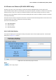
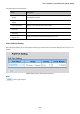
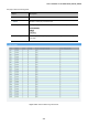
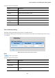
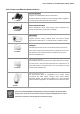
Table Of Contents
- 1. INTRODUCTION
- 2. INSTALLATION
- 3. SWITCH MANAGEMENT
- 4. WEB CONFIGURATION
- 4.1 Main Web Page
- 4.2 System
- 4.3 Port Management
- 4.4 Link Aggregation
- 4.5 VLAN
- 4.5.1 VLAN Overview
- 4.5.2 IEEE 802.1Q VLAN
- 4.5.3 Management VLAN
- 4.5.4 Create VLAN
- 4.5.5 Interface Settings
- 4.5.6 Port to VLAN
- 4.5.7 Port VLAN Membership
- 4.5.8 Protocol VLAN Group Setting
- 4.5.9 Protocol VLAN Port Setting
- 4.5.10 GVRP Setting
- 4.5.11 GVRP Port Setting
- 4.5.12 GVRP VLAN
- 4.5.13 GVRP Statistics
- 4.5.14 VLAN setting example:
- 4.6 Spanning Tree Protocol
- 4.7 Multicast
- 4.8 Quality of Service
- 4.9 Security
- 4.10 ACL
- 4.11 MAC Address Table
- 4.12 LLDP
- 4.13 Diagnostics
- 4.14 Power over Ethernet (GS-4210-24P2S only)
- 4.15 RMON
- 4.16 Maintenance
- 5. COMMAND LINE INTERFACE
- 6. Command Line Mode
- 6.1 User Mode Commands
- 6.2 Privileged Mode Commands
- 6.2.1 clear command
- 6.2.2 clock command
- 6.2.3 configure command
- 6.2.4 copy command
- 6.2.5 debug command
- 6.2.6 delete command
- 6.2.7 disable command
- 6.2.8 end command
- 6.2.9 exit command
- 6.2.10 no command
- 6.2.11 ping command
- 6.2.12 reboot command
- 6.2.13 renew command
- 6.2.14 restore-defaults command
- 6.2.15 save command
- 6.2.16 show command
- 6.2.17 ssl command
- 6.2.18 traceroute command
- 6.2.19 udld command
- 6.3 Global Config Mode Commands
- 6.3.1 aaa Command
- 6.3.2 boot Command
- 6.3.3 bridge Command
- 6.3.4 class-map Command
- 6.3.5 clock Command
- 6.3.6 dos Command
- 6.3.7 dot1x Command
- 6.3.8 do Command
- 6.3.9 enable Command
- 6.3.10 end Command
- 6.3.11 errdisable Command
- 6.3.12 exit Command
- 6.3.13 gvrp Command
- 6.3.14 hostname Command
- 6.3.15 interface Command
- 6.3.16 ip Command
- 6.3.17 ipv6 Command
- 6.3.18 jumbo-frame Command
- 6.3.19 l2 Command
- 6.3.20 lacp Command
- 6.3.21 lag Command
- 6.3.22 line Command
- 6.3.23 lldp Command
- 6.3.24 logging Command
- 6.3.25 mac Command
- 6.3.26 management-vlan Command
- 6.3.27 mirror Command
- 6.3.28 no Command
- 6.3.29 policy-map Command
- 6.3.30 port-security Command
- 6.3.31 qos Command
- 6.3.32 radius Command
- 6.3.33 rate-limit Command
- 6.3.34 rmon Command
- 6.3.35 Snmp Command
- 6.3.36 sntp Command
- 6.3.37 spanning-tree Command
- 6.3.38 storm-control Command
- 6.3.39 system Command
- 6.3.40 tacacs Command
- 6.3.41 udld Command
- 6.3.42 username Command
- 6.3.43 vlan Command
- 6.3.44 voice-vlan Command
- 7. SWITCH OPERATION
- 8. POWER OVER ETHERNET OVERVIEW
- 9. TROUBLESHOOTING
- APPENDIX A
- EC Declaration of Conformity

User’s Manual of GS-4210-16T2S_24T2S_24P2S
4.14.4 Power over Ethernet Powered Device
3~5 Watts
Voice over IP phones
Enterprise can install POE VoIP Phone, ATA and other
Ethernet/non-Ethernet end-devices to the central where UPS is installed for
un-interrupt power system and power control system.
6~12 Watts
Wireless LAN Access Points
Museum, Sightseeing, Airport, Hotel, Campus, Factory, Warehouse can
install the Access Point any where with no hesitation.
10~12 Watts
IP Surveillance
Enterprise, Museum, Campus, Hospital, Bank, can install IP Camera
without limits of install location – no need electrician to install AC sockets.
3~12 Watts
PoE Splitter
PoE Splitter split the PoE 52V DC over the Ethernet cable into 5/12V DC
power output. It frees the device deployment from restrictions due to power
outlet locations, which eliminate the costs for additional AC wiring and
reduces the installation time.
3~25 Watts
High Power PoE Splitter
High PoE Splitter split the PoE 52V DC over the Ethernet cable into 24/12V
DC power output. It frees the device deployment from restrictions due to
power outlet locations, which eliminate the costs for additional AC wiring
and reduces the installation time.
High Power Speed Dome
This state-of-the-art design is considerable to fit in various network
environments like traffic centers, shopping malls, railway stations,
warehouses, airports, and production facilities for the most demanding
outdoor surveillance applications- no need electrician to install AC sockets.
30 Watts
Since the GS-4210-24P2S PoE Managed Switch per PoE port supports 52V DC PoE power
output, please check and assure the Powered Device’s (PD) acceptable DC power range is
from 52V DC; otherwise, it will damage the Powered Device (PD).
349