
User's Manual
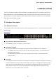
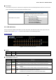
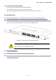
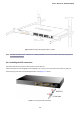
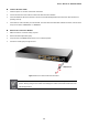
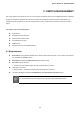
Table Of Contents
- 1. INTRODUCTION
- 2. INSTALLATION
- 3. SWITCH MANAGEMENT
- 4. WEB CONFIGURATION
- 4.1 Main Web Page
- 4.2 System
- 4.3 Port Management
- 4.4 Link Aggregation
- 4.5 VLAN
- 4.6 Spanning Tree Protocol
- 4.7 Multicast
- 4.8 Quality of Service
- 4.9 Security
- 4.10 ACL
- 4.11 MAC Address Table
- 4.12 LLDP
- 4.13 Diagnostics
- 4.14 Power over Ethernet
- 4.15 RMON
- 4.16 Maintenance
- 5. COMMAND LINE INTERFACE
- 6. Command Line Mode
- 6.1 User Mode Commands
- 6.2 Privileged Mode Commands
- 6.2.1 clear command
- 6.2.2 clock command
- 6.2.3 configure command
- 6.2.4 copy command
- 6.2.5 debug command
- 6.2.6 delete command
- 6.2.7 disable command
- 6.2.8 end command
- 6.2.9 exit command
- 6.2.10 no command
- 6.2.11 ping command
- 6.2.12 reboot command
- 6.2.13 renew command
- 6.2.14 restore-defaults command
- 6.2.15 save command
- 6.2.16 show command
- 6.2.17 ssl command
- 6.2.18 traceroute command
- 6.2.19 udld command
- 6.3 Global Config Mode Commands
- 6.3.1 aaa Command
- 6.3.2 boot Command
- 6.3.3 bridge Command
- 6.3.4 class-map Command
- 6.3.5 clock Command
- 6.3.6 dos Command
- 6.3.7 dot1x Command
- 6.3.8 do Command
- 6.3.9 enable Command
- 6.3.10 end Command
- 6.3.11 errdisable Command
- 6.3.12 exit Command
- 6.3.13 gvrp Command
- 6.3.14 hostname Command
- 6.3.15 interface Command
- 6.3.16 ip Command
- 6.3.17 ipv6 Command
- 6.3.18 jumbo-frame Command
- 6.3.19 l2 Command
- 6.3.20 lacp Command
- 6.3.21 lag Command
- 6.3.22 line Command
- 6.3.23 lldp Command
- 6.3.24 logging Command
- 6.3.25 mac Command
- 6.3.26 management-VLAN Command
- 6.3.27 mirror Command
- 6.3.28 no Command
- 6.3.29 policy-map Command
- 6.3.30 port-security Command
- 6.3.31 qos Command
- 6.3.32 radius Command
- 6.3.33 rate-limit Command
- 6.3.34 rmon Command
- 6.3.35 Snmp Command
- 6.3.36 sntp Command
- 6.3.37 spanning-tree Command
- 6.3.38 storm-control Command
- 6.3.39 system Command
- 6.3.40 tacacs Command
- 6.3.41 udld Command
- 6.3.42 username Command
- 6.3.43 vlan Command
- 6.3.44 voice-vlan Command
- 7. SWITCH OPERATION
- 8. POWER OVER ETHERNET OVERVIEW
- 9. TROUBLESHOOTING
- APPENDIX A
- EC Declaration of Conformity

User’s Manual of GS-4210-24P2S
21
2. INSTALLATION
This section describes the hardware features and installation of the PoE Managed Switch on the desktop or rack mount. For
easier management and control of the PoE Managed Switch, familiarize yourself with its display indicators, and ports. Front
panel illustrations in this chapter display the unit LED indicators. Before connecting any network device to the PoE Managed
Switch, please read this chapter completely.
2.1 Hardware Description
2.1.1 Switch Front Panel
The front panel provides a simple interface monitoring the PoE Managed Switch. Figure 2-1-1 shows the front panel of the PoE
Managed Switch.
Front Panel
Figure 2-1-1: GS-4210-24P2S Front Panel
■ Gigabit TP Interface (802.3af / 802.3at PoE Injector)
10/100/1000Base-T Copper, RJ-45 Twist-Pair: Up to 100 meters.
■ 100/1000Base-X SFP Slots
Each of the SFP (Small Form-factor Pluggable) slot supports Dual-speed, 1000Base-SX / LX or 100Base-FX
- For 1000Base-SX/LX SFP transceiver module: From 550 meters (Multi-mode fiber), up to 10/30/40/50/70/120
kilometers (Single-mode fiber).
- For 100Base-FX SFP transceiver module: From 2 kilometers (Multi-mode fiber), up to 20/40/60 kilometers
(Single-mode fiber).
■ Console Port
The console port is a RJ-45 port connector. It is an interface for connecting a terminal directly. Through the console port, it
provides rich diagnostic information including IP Address setting, factory reset, port management, link status and system
setting. Users can use the attached DB9 to RJ-45 console cable in the package and connect to the console port on the
device. After the connection, users can run any terminal emulation program (Hyper Terminal, ProComm Plus, Telix,
Winterm and so on) to enter the startup screen of the device.