
User's Manual
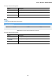
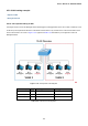
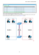
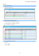
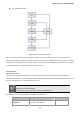
Table Of Contents
- 1. INTRODUCTION
- 2. INSTALLATION
- 3. SWITCH MANAGEMENT
- 4. WEB CONFIGURATION
- 4.1 Main Web Page
- 4.2 System
- 4.3 Port Management
- 4.4 Link Aggregation
- 4.5 VLAN
- 4.6 Spanning Tree Protocol
- 4.7 Multicast
- 4.8 Quality of Service
- 4.9 Security
- 4.10 ACL
- 4.11 MAC Address Table
- 4.12 LLDP
- 4.13 Diagnostics
- 4.14 Power over Ethernet
- 4.15 RMON
- 4.16 Maintenance
- 5. COMMAND LINE INTERFACE
- 6. Command Line Mode
- 6.1 User Mode Commands
- 6.2 Privileged Mode Commands
- 6.2.1 clear command
- 6.2.2 clock command
- 6.2.3 configure command
- 6.2.4 copy command
- 6.2.5 debug command
- 6.2.6 delete command
- 6.2.7 disable command
- 6.2.8 end command
- 6.2.9 exit command
- 6.2.10 no command
- 6.2.11 ping command
- 6.2.12 reboot command
- 6.2.13 renew command
- 6.2.14 restore-defaults command
- 6.2.15 save command
- 6.2.16 show command
- 6.2.17 ssl command
- 6.2.18 traceroute command
- 6.2.19 udld command
- 6.3 Global Config Mode Commands
- 6.3.1 aaa Command
- 6.3.2 boot Command
- 6.3.3 bridge Command
- 6.3.4 class-map Command
- 6.3.5 clock Command
- 6.3.6 dos Command
- 6.3.7 dot1x Command
- 6.3.8 do Command
- 6.3.9 enable Command
- 6.3.10 end Command
- 6.3.11 errdisable Command
- 6.3.12 exit Command
- 6.3.13 gvrp Command
- 6.3.14 hostname Command
- 6.3.15 interface Command
- 6.3.16 ip Command
- 6.3.17 ipv6 Command
- 6.3.18 jumbo-frame Command
- 6.3.19 l2 Command
- 6.3.20 lacp Command
- 6.3.21 lag Command
- 6.3.22 line Command
- 6.3.23 lldp Command
- 6.3.24 logging Command
- 6.3.25 mac Command
- 6.3.26 management-VLAN Command
- 6.3.27 mirror Command
- 6.3.28 no Command
- 6.3.29 policy-map Command
- 6.3.30 port-security Command
- 6.3.31 qos Command
- 6.3.32 radius Command
- 6.3.33 rate-limit Command
- 6.3.34 rmon Command
- 6.3.35 Snmp Command
- 6.3.36 sntp Command
- 6.3.37 spanning-tree Command
- 6.3.38 storm-control Command
- 6.3.39 system Command
- 6.3.40 tacacs Command
- 6.3.41 udld Command
- 6.3.42 username Command
- 6.3.43 vlan Command
- 6.3.44 voice-vlan Command
- 7. SWITCH OPERATION
- 8. POWER OVER ETHERNET OVERVIEW
- 9. TROUBLESHOOTING
- APPENDIX A
- EC Declaration of Conformity

User’s Manual of GS-4210-24P2S
4.5.9 VLAN setting example:
- Separate VLANs
- 802.1Q VLAN Trunk
4.5.9.1 Two separate 802.1Q VLANs
The diagram shows how the PoE Managed Switch handle Tagged and Untagged traffic flow for two VLANs. VLAN Group 2 and
VLAN Group 3 are separated VLANs. Each VLAN isolate network traffic so only members of the VLAN receive traffic from the
same VLAN members. The screen in Figure 4-5-11 appears and Table 4-5-2 describes the port configuration of the PoE
Managed Switches.
Figure 4-5-11: Two Separate VLAN Diagrams
VLAN Group VID Untagged Members Tagged Members
VLAN Group 1 1 Port-7~Port-8 N/A
VLAN Group 2 2 Port-1,Port-2 Port-3
VLAN Group 3 3 Port-4,Port-5 Port-6
Table 4-5-2: VLAN and Port Configuration
112