
User's Manual
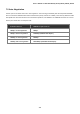
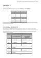
Table Of Contents
- 1. INTRODUCTION
- 2. INSTALLATION
- 3. SWITCH MANAGEMENT
- 4. WEB CONFIGURATION
- 4.1 Main Web Page
- 4.2 System
- 4.3 Port Management
- 4.4 Link Aggregation
- 4.5 VLAN
- 4.5.1 VLAN Overview
- 4.5.2 IEEE 802.1Q VLAN
- 4.5.3 Management VLAN
- 4.5.4 Create VLAN
- 4.5.5 Interface Settings
- 4.5.6 Port to VLAN
- 4.5.7 Port VLAN Membership
- 4.5.8 Protocol VLAN Group Setting
- 4.5.9 Protocol VLAN Port Setting
- 4.5.10 GVRP Setting
- 4.5.11 GVRP Port Setting
- 4.5.12 GVRP VLAN
- 4.5.13 GVRP Statistics
- 4.5.14 VLAN setting example:
- 4.6 Spanning Tree Protocol
- 4.7 Multicast
- 4.8 Quality of Service
- 4.9 Security
- 4.10 ACL
- 4.11 MAC Address Table
- 4.12 LLDP
- 4.13 Diagnostics
- 4.14 Power over Ethernet (GS-4210-16P2S and GS-4210-24P2S only)
- 4.15 RMON
- 4.16 Maintenance
- 5. COMMAND LINE INTERFACE
- 6. Command Line Mode
- 6.1 User Mode Commands
- 6.2 Privileged Mode Commands
- 6.2.1 clear command
- 6.2.2 clock command
- 6.2.3 configure command
- 6.2.4 copy command
- 6.2.5 debug command
- 6.2.6 delete command
- 6.2.7 disable command
- 6.2.8 end command
- 6.2.9 exit command
- 6.2.10 no command
- 6.2.11 ping command
- 6.2.12 reboot command
- 6.2.13 renew command
- 6.2.14 restore-defaults command
- 6.2.15 save command
- 6.2.16 show command
- 6.2.17 ssl command
- 6.2.18 traceroute command
- 6.2.19 udld command
- 6.3 Global Config Mode Commands
- 6.3.1 aaa Command
- 6.3.2 boot Command
- 6.3.3 bridge Command
- 6.3.4 class-map Command
- 6.3.5 clock Command
- 6.3.6 dos Command
- 6.3.7 dot1x Command
- 6.3.8 do Command
- 6.3.9 enable Command
- 6.3.10 end Command
- 6.3.11 errdisable Command
- 6.3.12 exit Command
- 6.3.13 gvrp Command
- 6.3.14 hostname Command
- 6.3.15 interface Command
- 6.3.16 ip Command
- 6.3.17 ipv6 Command
- 6.3.18 jumbo-frame Command
- 6.3.19 l2 Command
- 6.3.20 lacp Command
- 6.3.21 lag Command
- 6.3.22 line Command
- 6.3.23 lldp Command
- 6.3.24 logging Command
- 6.3.25 mac Command
- 6.3.26 management-vlan Command
- 6.3.27 mirror Command
- 6.3.28 no Command
- 6.3.29 policy-map Command
- 6.3.30 port-security Command
- 6.3.31 qos Command
- 6.3.32 radius Command
- 6.3.33 rate-limit Command
- 6.3.34 rmon Command
- 6.3.35 Snmp Command
- 6.3.36 sntp Command
- 6.3.37 spanning-tree Command
- 6.3.38 storm-control Command
- 6.3.39 system Command
- 6.3.40 tacacs Command
- 6.3.41 udld Command
- 6.3.42 username Command
- 6.3.43 vlan Command
- 6.3.44 voice-vlan Command
- 7. SWITCH OPERATION
- 8. POWER OVER ETHERNET OVERVIEW
- 9. TROUBLESHOOTING
- APPENDIX A

User’s Manual of GS-4210-16T2S_24T2S_16P2S_24P2S_48T4S
430
APPENDIX A
A.1 Switch's RJ45 Pin Assignments 1000Mbps, 1000BASE-T
Contact MDI MDI-X
1 BI_DA+ BI_DB+
2 BI_DA- BI_DB-
3 BI_DB+ BI_DA+
4 BI_DC+ BI_DD+
5 BI_DC- BI_DD-
6 BI_DB- BI_DA-
7 BI_DD+ BI_DC+
8 BI_DD- BI_DC-
Implicit implementation of the crossover function within a twisted-pair cable, or at a wiring panel, while not expressly forbidden,
is beyond the scope of this standard.
A.2 10/100Mbps, 10/100BASE-TX
When connecting your 10/100Mbps Ethernet Switch to another switch, a bridge or a hub, a straight or crossover cable is
necessary. Each port of the Switch supports auto-MDI/MDI-X detection. That means you can directly connect the Switch to any
Ethernet devices without making a crossover cable. The following table and diagram show the standard RJ45 receptacle/
connector and their pin assignments:
RJ45 Connector pin assignment
Contact MDI
Media Dependent Interface
MDI-X
Media Dependent
Interface-Cross
1 Tx + (transmit) Rx + (receive)
2 Tx - (transmit) Rx - (receive)
3 Rx + (receive) Tx + (transmit)
4, 5 Not used
6 Rx - (receive) Tx - (transmit)
7, 8 Not used