
User's Manual

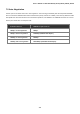
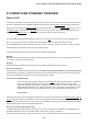
Table Of Contents
- 1. INTRODUCTION
- 2. INSTALLATION
- 3. SWITCH MANAGEMENT
- 4. WEB CONFIGURATION
- 4.1 Main Web Page
- 4.2 System
- 4.3 Port Management
- 4.4 Link Aggregation
- 4.5 VLAN
- 4.5.1 VLAN Overview
- 4.5.2 IEEE 802.1Q VLAN
- 4.5.3 Management VLAN
- 4.5.4 Create VLAN
- 4.5.5 Interface Settings
- 4.5.6 Port to VLAN
- 4.5.7 Port VLAN Membership
- 4.5.8 Protocol VLAN Group Setting
- 4.5.9 Protocol VLAN Port Setting
- 4.5.10 GVRP Setting
- 4.5.11 GVRP Port Setting
- 4.5.12 GVRP VLAN
- 4.5.13 GVRP Statistics
- 4.5.14 VLAN setting example:
- 4.6 Spanning Tree Protocol
- 4.7 Multicast
- 4.8 Quality of Service
- 4.9 Security
- 4.10 ACL
- 4.11 MAC Address Table
- 4.12 LLDP
- 4.13 Diagnostics
- 4.14 Power over Ethernet (GS-4210-16P2S and GS-4210-24P2S only)
- 4.15 RMON
- 4.16 Maintenance
- 5. COMMAND LINE INTERFACE
- 6. Command Line Mode
- 6.1 User Mode Commands
- 6.2 Privileged Mode Commands
- 6.2.1 clear command
- 6.2.2 clock command
- 6.2.3 configure command
- 6.2.4 copy command
- 6.2.5 debug command
- 6.2.6 delete command
- 6.2.7 disable command
- 6.2.8 end command
- 6.2.9 exit command
- 6.2.10 no command
- 6.2.11 ping command
- 6.2.12 reboot command
- 6.2.13 renew command
- 6.2.14 restore-defaults command
- 6.2.15 save command
- 6.2.16 show command
- 6.2.17 ssl command
- 6.2.18 traceroute command
- 6.2.19 udld command
- 6.3 Global Config Mode Commands
- 6.3.1 aaa Command
- 6.3.2 boot Command
- 6.3.3 bridge Command
- 6.3.4 class-map Command
- 6.3.5 clock Command
- 6.3.6 dos Command
- 6.3.7 dot1x Command
- 6.3.8 do Command
- 6.3.9 enable Command
- 6.3.10 end Command
- 6.3.11 errdisable Command
- 6.3.12 exit Command
- 6.3.13 gvrp Command
- 6.3.14 hostname Command
- 6.3.15 interface Command
- 6.3.16 ip Command
- 6.3.17 ipv6 Command
- 6.3.18 jumbo-frame Command
- 6.3.19 l2 Command
- 6.3.20 lacp Command
- 6.3.21 lag Command
- 6.3.22 line Command
- 6.3.23 lldp Command
- 6.3.24 logging Command
- 6.3.25 mac Command
- 6.3.26 management-vlan Command
- 6.3.27 mirror Command
- 6.3.28 no Command
- 6.3.29 policy-map Command
- 6.3.30 port-security Command
- 6.3.31 qos Command
- 6.3.32 radius Command
- 6.3.33 rate-limit Command
- 6.3.34 rmon Command
- 6.3.35 Snmp Command
- 6.3.36 sntp Command
- 6.3.37 spanning-tree Command
- 6.3.38 storm-control Command
- 6.3.39 system Command
- 6.3.40 tacacs Command
- 6.3.41 udld Command
- 6.3.42 username Command
- 6.3.43 vlan Command
- 6.3.44 voice-vlan Command
- 7. SWITCH OPERATION
- 8. POWER OVER ETHERNET OVERVIEW
- 9. TROUBLESHOOTING
- APPENDIX A
User’s Manual of GS-4210-16T2S_24T2S_16P2S_24P2S_48T4S
429
9. TROUBLESHOOTING
This chapter contains information to help you solve your issue. If the Managed Switch is not functioning properly, make sure the
Managed Switch is set up according to instructions in this manual.
■ The Link LED is not lit
Solution:
Check the cable connection and remove duplex mode of the Managed Switch.
■ Some stations cannot talk to other stations located on the other port
Solution:
Please check the VLAN settings, trunk settings, or port enabled/disabled status.
■ Performance is bad
Solution:
Check the full duplex status of the Managed Switch. If the Managed Switch is set to full duplex and the partner is set to half
duplex, then the performance will be poor. Please also check the in/out rate of the port.
■ Why the Switch doesn't connect to the network
Solution:
1. Check the LNK/ACT LED on the Managed Switch.
2. Try another port on the Managed Switch.
3. Make sure the cable is installed properly.
4. Make sure the cable is the right type.
5. Turn off the power. After a while, turn on power again.
■ 100BASE-TX port link LED is lit, but the traffic is irregular
Solution:
Check that the attached device is not set to dedicate full duplex. Some devices use a physical or software switch to change
duplex modes. Auto-negotiation may not recognize this type of full-duplex setting.
■ Switch does not power up
Solution:
1. AC power cord not inserted or faulty
2. Check whether the AC power cord is inserted correctly
3. Replace the power cord if the cord is inserted correctly, check that the AC power source is working by connecting a
different device in place of the switch.
4. If that device works, refer to the next step.
5. If that device does not work, check the AC power