
User's Manual
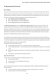
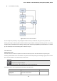
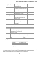
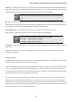
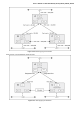
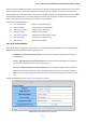
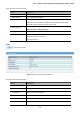
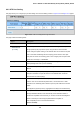
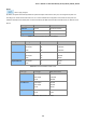
Table Of Contents
- 1. INTRODUCTION
- 2. INSTALLATION
- 3. SWITCH MANAGEMENT
- 4. WEB CONFIGURATION
- 4.1 Main Web Page
- 4.2 System
- 4.3 Port Management
- 4.4 Link Aggregation
- 4.5 VLAN
- 4.5.1 VLAN Overview
- 4.5.2 IEEE 802.1Q VLAN
- 4.5.3 Management VLAN
- 4.5.4 Create VLAN
- 4.5.5 Interface Settings
- 4.5.6 Port to VLAN
- 4.5.7 Port VLAN Membership
- 4.5.8 Protocol VLAN Group Setting
- 4.5.9 Protocol VLAN Port Setting
- 4.5.10 GVRP Setting
- 4.5.11 GVRP Port Setting
- 4.5.12 GVRP VLAN
- 4.5.13 GVRP Statistics
- 4.5.14 VLAN setting example:
- 4.6 Spanning Tree Protocol
- 4.7 Multicast
- 4.8 Quality of Service
- 4.9 Security
- 4.10 ACL
- 4.11 MAC Address Table
- 4.12 LLDP
- 4.13 Diagnostics
- 4.14 Power over Ethernet (GS-4210-16P2S and GS-4210-24P2S only)
- 4.15 RMON
- 4.16 Maintenance
- 5. COMMAND LINE INTERFACE
- 6. Command Line Mode
- 6.1 User Mode Commands
- 6.2 Privileged Mode Commands
- 6.2.1 clear command
- 6.2.2 clock command
- 6.2.3 configure command
- 6.2.4 copy command
- 6.2.5 debug command
- 6.2.6 delete command
- 6.2.7 disable command
- 6.2.8 end command
- 6.2.9 exit command
- 6.2.10 no command
- 6.2.11 ping command
- 6.2.12 reboot command
- 6.2.13 renew command
- 6.2.14 restore-defaults command
- 6.2.15 save command
- 6.2.16 show command
- 6.2.17 ssl command
- 6.2.18 traceroute command
- 6.2.19 udld command
- 6.3 Global Config Mode Commands
- 6.3.1 aaa Command
- 6.3.2 boot Command
- 6.3.3 bridge Command
- 6.3.4 class-map Command
- 6.3.5 clock Command
- 6.3.6 dos Command
- 6.3.7 dot1x Command
- 6.3.8 do Command
- 6.3.9 enable Command
- 6.3.10 end Command
- 6.3.11 errdisable Command
- 6.3.12 exit Command
- 6.3.13 gvrp Command
- 6.3.14 hostname Command
- 6.3.15 interface Command
- 6.3.16 ip Command
- 6.3.17 ipv6 Command
- 6.3.18 jumbo-frame Command
- 6.3.19 l2 Command
- 6.3.20 lacp Command
- 6.3.21 lag Command
- 6.3.22 line Command
- 6.3.23 lldp Command
- 6.3.24 logging Command
- 6.3.25 mac Command
- 6.3.26 management-vlan Command
- 6.3.27 mirror Command
- 6.3.28 no Command
- 6.3.29 policy-map Command
- 6.3.30 port-security Command
- 6.3.31 qos Command
- 6.3.32 radius Command
- 6.3.33 rate-limit Command
- 6.3.34 rmon Command
- 6.3.35 Snmp Command
- 6.3.36 sntp Command
- 6.3.37 spanning-tree Command
- 6.3.38 storm-control Command
- 6.3.39 system Command
- 6.3.40 tacacs Command
- 6.3.41 udld Command
- 6.3.42 username Command
- 6.3.43 vlan Command
- 6.3.44 voice-vlan Command
- 7. SWITCH OPERATION
- 8. POWER OVER ETHERNET OVERVIEW
- 9. TROUBLESHOOTING
- APPENDIX A

User’s Manual of GS-4210-16T2S_24T2S_16P2S_24P2S_48T4S
153
From disabled to blocking
Figure 4-6-1: STP Port State Transitions
You can modify each port state by using management software. When you enable STP, every port on every switch in the
network goes through the blocking state and then transitions through the states of listening and learning at power up. If properly
configured, each port stabilizes to the forwarding or blocking state. No packets (except BPDUs) are forwarded from, or received
by, STP enabled ports until the forwarding state is enabled for that port.
2. STP Parameters
STP Operation Levels
The Switch allows for two levels of operation: the switch level and the port level. The switch level forms a spanning tree
consisting of links between one or more switches. The port level constructs a spanning tree consisting of groups of one or more
ports. The STP operates in much the same way for both levels.
On the switch level, STP calculates the Bridge Identifier for each switch and then sets the Root
Bridge and the Designated Bridges.
On the port level, STP sets the Root Port and the Designated Ports.
The following are the user-configurable STP parameters for the switch level:
Parameter Description Default Value
Bridge Identifier(Not user
configurable
A combination of the User-set priority and
the switch’s MAC address.
32768 + MAC