
GS-4210 Series User Manual
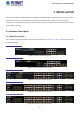
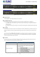
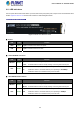
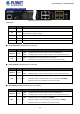
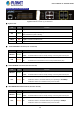
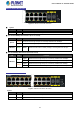
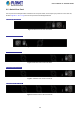
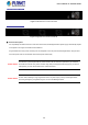
Table Of Contents
- 1. INTRODUCTION
- 2. INSTALLATION
- 3. SWITCH MANAGEMENT
- 4. WEB CONFIGURATION
- 4.1 Main Web Page
- 4.2 System
- 4.3 Port Management
- 4.4 Link Aggregation
- 4.5 VLAN
- 4.5.1 VLAN Overview
- 4.5.2 IEEE 802.1Q VLAN
- 4.5.3 Management VLAN
- 4.5.4 Create VLAN
- 4.5.5 Interface Settings
- 4.5.6 Port to VLAN
- 4.5.7 Port VLAN Membership
- 4.5.8 Protocol VLAN Group Setting
- 4.5.9 Protocol VLAN Port Setting
- 4.5.10 GVRP Setting
- 4.5.11 GVRP Port Setting
- 4.5.12 GVRP VLAN
- 4.5.13 GVRP Statistics
- 4.5.14 VLAN setting example:
- 4.6 Spanning Tree Protocol
- 4.7 Multicast
- 4.8 Quality of Service
- 4.9 Security
- 4.10 ACL
- 4.11 MAC Address Table
- 4.12 LLDP
- 4.13 Diagnostics
- 4.14 RMON
- 4.15 Power over Ethernet
- 4.16 Maintenance
- 5. SWITCH OPERATION
- 6. TROUBLESHOOTING
- APPENDIX A Switch's RJ45 Pin Assignments

User’s Manual of GS-4210 Series
2. INSTALLATION
This section describes the hardware features and installation of the Managed Switch on the desktop or rack mount. For easier
management and control of the Managed Switch, familiarize yourself with its display indicators and ports. Front panel
illustrations in this chapter display the unit LED indicators. Before connecting any network device to the Managed Switch, please
read this chapter completely.
2.1 Hardware Description
2.1.1 Switch Front Panel
The front panel provides a simple interface monitoring of the Managed Switch. Figures 2-1-1a to 2-1-1g show the front panels of
the Managed Switches.
GS-4210-8P2S Front Panel
Figure 2-1-1a GS-4210-8P2S
Front Panel
GS-4210-8P2T2S Front Panel
Fi
gure 2-1-1b GS-4210-8P2T2S Front Panel
GS-4210-16P4C Front Panel
Figure 2-1-1c GS-4210-16P4C Front Panel
GS-4210-24P4C Front Panel
Figure 2-1-1d GS-4210-24P4C Front Panel
GS-4210-24PL4C Front Panel
Fig
ure 2-1-1e GS-4210-24PL4C Front Panel
31