
GS-4210 Series User Manual
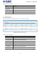
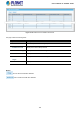
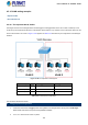
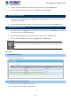
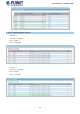
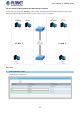
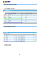
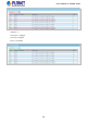
Table Of Contents
- 1. INTRODUCTION
- 2. INSTALLATION
- 3. SWITCH MANAGEMENT
- 4. WEB CONFIGURATION
- 4.1 Main Web Page
- 4.2 System
- 4.3 Port Management
- 4.4 Link Aggregation
- 4.5 VLAN
- 4.5.1 VLAN Overview
- 4.5.2 IEEE 802.1Q VLAN
- 4.5.3 Management VLAN
- 4.5.4 Create VLAN
- 4.5.5 Interface Settings
- 4.5.6 Port to VLAN
- 4.5.7 Port VLAN Membership
- 4.5.8 Protocol VLAN Group Setting
- 4.5.9 Protocol VLAN Port Setting
- 4.5.10 GVRP Setting
- 4.5.11 GVRP Port Setting
- 4.5.12 GVRP VLAN
- 4.5.13 GVRP Statistics
- 4.5.14 VLAN setting example:
- 4.6 Spanning Tree Protocol
- 4.7 Multicast
- 4.8 Quality of Service
- 4.9 Security
- 4.10 ACL
- 4.11 MAC Address Table
- 4.12 LLDP
- 4.13 Diagnostics
- 4.14 RMON
- 4.15 Power over Ethernet
- 4.16 Maintenance
- 5. SWITCH OPERATION
- 6. TROUBLESHOOTING
- APPENDIX A Switch's RJ45 Pin Assignments

User’s Manual of GS-4210 Series
3. When the packet leaves Port-2, it will be stripped away by its tag becoming an untagged packet.
4. When the packet leaves Port-3, it will be kept as a tagged packet with VLAN Tag=2.
Tagged packet entering VLAN 2
1. When PC-3 transmits a tagged packet with VLAN Tag=2 entering Port-3, PC-1 and PC-2 will receive the packet
through Port-1 and Port-2.
2. When the packet leaves Port-1 and Port-2, it will be stripped away by its tag becoming an untagged packet.
Untagged packet entering VLAN 3
1. When PC-4 transmits an untagged packet entering Port-4, the switch will tag it with a VLAN Tag=3. PC-5 and PC-6
will receive the packet through Port-5 and Port-6.
2. When the packet leaves Port-5, it will be stripped away by its tag becoming an untagged packet.
3. When the packet leaves Port-6, it will be kept as a tagged packet with VLAN Tag=3.
In this example, VLAN Group 1 is set as default VLAN, but only focuses on VLAN 2 and VLAN 3 traffic
flow.
Setup Steps
1. Create VLAN Group 2 and 3
Add VLAN group 2 and group 3
2. Assign VLAN mode and PVID to each port:
Port-1, Port-2 and Port-3: VLAN Mode = Hybrid, PVID=2
Port-4, Port-5 and Port-6: VLAN Mode = Hybrid, PVID=3
144