
GS-4210-Series (V2) User Manual
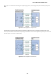
Table Of Contents
- 1. INTRODUCTION
- 2. INSTALLATION
- 3. SWITCH MANAGEMENT
- 4. WEB CONFIGURATION
- 4.1 Main Web Page
- 4.2 System
- 4.3 Switching
- 4.3.1 Port Management
- 4.3.1.1 Port Configuration
- 4.3.1.2 Port Counters
- 4.3.1.3 Bandwidth Utilization
- 4.3.1.4 Port Mirroring
- 4.3.1.5 Jumbo Frame
- 4.3.1.6 Port Error Disabled Configuration
- 4.3.1.7 Port Error Disabled Status
- 4.3.1.8 Protected Ports
- 4.3.1.9 EEE
- 4.3.2 Link Aggregation
- 4.3.2.1 LAG Setting
- 4.3.2.2 LAG Management
- 4.3.2.3 LAG Port Setting
- 4.3.2.4 LACP Setting
- 4.3.2.5 LACP Port Setting
- 4.3.2.6 LAG Status
- 4.3.3 VLAN
- 4.3.3.1 VLAN Overview
- 4.3.3.2 IEEE 802.1Q VLAN
- 4.3.3.3 Management VLAN
- 4.3.3.4 Create VLAN
- 4.3.3.5 Interface Settings
- 4.3.3.6 Port to VLAN
- 4.3.3.7 Port VLAN Membership
- 4.3.3.8 Protocol VLAN Group Setting
- 4.3.3.9 Protocol VLAN Port Setting
- 4.3.3.10 GVRP Setting
- 4.3.3.11 GVRP Port Setting
- 4.3.3.12 GVRP VLAN
- 4.3.3.13 GVRP Statistics
- 4.3.3.14 VLAN setting example:
- 4.3.3.14.1 Two separate 802.1Q VLANs
- 4.3.3.14.2 VLAN Trunking between two 802.1Q aware switches
- 4.3.4 Spanning Tree Protocol
- 4.3.5 Multicast
- 4.3.6 IGMP Snooping
- 4.3.7 MLD Snooping
- 4.3.8 LLDP
- 4.3.9 MAC Address Table
- 4.3.1 Port Management
- 4.4 Quality of Service
- 4.5 Security
- 4.6 Ring
- 4.7 Power over Ethernet
- 4.8 Maintenance
- 5. COMMAND LINE INTERFACE
- 6. Command Line Mode
- 6.1 User Mode Commands
- 6.2 Privileged Mode Commands
- 6.2.1 clear command
- 6.2.2 clock command
- 6.2.3 configure command
- 6.2.4 copy command
- 6.2.5 delete command
- 6.2.6 disable command
- 6.2.7 end command
- 6.2.8 exit command
- 6.2.9 ping command
- 6.2.10 reboot command
- 6.2.11 renew command
- 6.2.12 restore-defaults command
- 6.2.13 save command
- 6.2.14 show command
- 6.2.15 ssl command
- 6.2.16 terminal command
- 6.3 Global Config Mode Commands
- 6.3.1 aaa Command
- 6.3.2 boot Command
- 6.3.3 clock Command
- 6.3.4 dos Command
- 6.3.5 dot1x Command
- 6.3.6 do Command
- 6.3.7 enable Command
- 6.3.8 end Command
- 6.3.9 erps Command
- 6.3.10 errdisable Command
- 6.3.11 exit Command
- 6.3.12 gvrp Command
- 6.3.13 hostname Command
- 6.3.14 interface Command
- 6.3.15 ip Command
- 6.3.16 ipv6 Command
- 6.3.17 jumbo-frame Command
- 6.3.18 lacp Command
- 6.3.19 lag Command
- 6.3.20 line Command
- 6.3.21 lldp Command
- 6.3.22 logging Command
- 6.3.23 mac Command
- 6.3.24 management Command
- 6.3.25 management-vlan Command
- 6.3.26 mirror Command
- 6.3.27 nms Command
- 6.3.28 no Command
- 6.3.29 poe Command
- 6.3.30 port-security Command
- 6.3.31 qos Command
- 6.3.32 radius Command
- 6.3.33 rmon Command
- 6.3.34 Snmp Command
- 6.3.35 sntp Command
- 6.3.36 spanning-tree Command
- 6.3.37 storm-control Command
- 6.3.38 system Command
- 6.3.39 tacacs Command
- 6.3.40 username Command
- 6.3.41 vlan Command
- 6.3.42 voice-vlan Command
- 7. SWITCH OPERATION
- 8. POWER OVER ETHERNET OVERVIEW
- 9. TROUBLESHOOTING
- APPENDIX A

User’s Manual of GS-4210 Series
389
8. POWER OVER ETHERNET OVERVIEW
What is PoE?
The PoE is an abbreviation of Power over Ethernet; the PoE technology means a system to pass electrical power safely, along
with data on Ethernet UTP cable. The IEEE standard for PoE technology requires Category 5 cable or higher for high power
PoE levels, but can operate with category 3 cable for low power levels. Power is supplied in common mode over two or more of
the differential pairs of wires found in the Ethernet cables and comes from a power supply within a PoE-enabled networking
device such as an Ethernet switch or can be injected into a cable run with a mid-span power supply.
The original IEEE 802.3af-2003 PoE standard provides up to 15.4 W of DC power (minimum 44 V DC and 350mA) to each
device. Only 12.95 W is assured to be available at the powered device as some power is dissipated in the cable.
The updated IEEE 802.3at-2009 PoE standard also known as PoE+ or PoE plus, provides up to 25.5 W of power. The 2009
standard prohibits a powered device from using all four pairs for power
The 802.3af/802.3at define two types of source equipment: Mid-Span and End-Span.
Mid-Span
Mid-Span device is placed between legacy switch and the powered device. Mid-Span is tap the unused wire pairs 4/5 and 7/8 to
carry power, the other four is for data transmit.
End-Span
End-Span device is direct connecting with power device. End-Span could also tap the wire 1/2 and 3/6.
PoE System Architecture
The specification of PoE typically requires two devices: the Powered Source Equipment (PSE) and the Powered Device (PD).
The PSE is either an End-Span or a Mid-Span, while the PD is a PoE-enabled terminal, such as IP Phones, Wireless LAN, etc.
Power can be delivered over data pairs or spare pairs of standard CAT-5 cabling.
Powered Source Equipment (PSE)
Power sourcing equipment (PSE) is a device such as a switch
that provides (sources) power on the Ethernet
cable. The maximum allowed continuous output power per cable in IEEE 802.3af is 15.40 W. A later
specification, IEEE 802.3at, offers 25.50 W. When the device is a switch, it is commonly called an End-span
(although IEEE 802.3af refers to it as endpoint). Otherwise, if it's an intermediary device between a non PoE
capable switch and a PoE device, it's called a Mid-span. An external PoE injector is a Mid-span device
.
Powered device
A powered device (PD) is a device powered by a PSE and thus consumes energy. Examples include wireless access points, IP
Phones, and IP cameras. Many powered devices have an auxiliary power connector for an optional, external, power supply.
Depending on the PD design, some, none, or all power can be supplied from the auxiliary port, with the auxiliary port sometimes
acting as backup power in case of PoE supplied power failure.
How Power is Transferred Through the Cable
A standard CAT5 Ethernet cable has four twisted pairs, but only two of these are used for 10BASE-T and 100BASE-TX. The
specification allows two options for using these cables for power, shown in Figure 1 and Figure 2:
The spare pairs are used. Figure 1 shows the pair on pins 4 and 5 connected together and forming the positive supply, and the