
GS-4210-Series (V2) User Manual
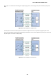
Table Of Contents
- 1. INTRODUCTION
- 2. INSTALLATION
- 3. SWITCH MANAGEMENT
- 4. WEB CONFIGURATION
- 4.1 Main Web Page
- 4.2 System
- 4.3 Switching
- 4.3.1 Port Management
- 4.3.1.1 Port Configuration
- 4.3.1.2 Port Counters
- 4.3.1.3 Bandwidth Utilization
- 4.3.1.4 Port Mirroring
- 4.3.1.5 Jumbo Frame
- 4.3.1.6 Port Error Disabled Configuration
- 4.3.1.7 Port Error Disabled Status
- 4.3.1.8 Protected Ports
- 4.3.1.9 EEE
- 4.3.2 Link Aggregation
- 4.3.2.1 LAG Setting
- 4.3.2.2 LAG Management
- 4.3.2.3 LAG Port Setting
- 4.3.2.4 LACP Setting
- 4.3.2.5 LACP Port Setting
- 4.3.2.6 LAG Status
- 4.3.3 VLAN
- 4.3.3.1 VLAN Overview
- 4.3.3.2 IEEE 802.1Q VLAN
- 4.3.3.3 Management VLAN
- 4.3.3.4 Create VLAN
- 4.3.3.5 Interface Settings
- 4.3.3.6 Port to VLAN
- 4.3.3.7 Port VLAN Membership
- 4.3.3.8 Protocol VLAN Group Setting
- 4.3.3.9 Protocol VLAN Port Setting
- 4.3.3.10 GVRP Setting
- 4.3.3.11 GVRP Port Setting
- 4.3.3.12 GVRP VLAN
- 4.3.3.13 GVRP Statistics
- 4.3.3.14 VLAN setting example:
- 4.3.3.14.1 Two separate 802.1Q VLANs
- 4.3.3.14.2 VLAN Trunking between two 802.1Q aware switches
- 4.3.4 Spanning Tree Protocol
- 4.3.5 Multicast
- 4.3.6 IGMP Snooping
- 4.3.7 MLD Snooping
- 4.3.8 LLDP
- 4.3.9 MAC Address Table
- 4.3.1 Port Management
- 4.4 Quality of Service
- 4.5 Security
- 4.6 Ring
- 4.7 Power over Ethernet
- 4.8 Maintenance
- 5. COMMAND LINE INTERFACE
- 6. Command Line Mode
- 6.1 User Mode Commands
- 6.2 Privileged Mode Commands
- 6.2.1 clear command
- 6.2.2 clock command
- 6.2.3 configure command
- 6.2.4 copy command
- 6.2.5 delete command
- 6.2.6 disable command
- 6.2.7 end command
- 6.2.8 exit command
- 6.2.9 ping command
- 6.2.10 reboot command
- 6.2.11 renew command
- 6.2.12 restore-defaults command
- 6.2.13 save command
- 6.2.14 show command
- 6.2.15 ssl command
- 6.2.16 terminal command
- 6.3 Global Config Mode Commands
- 6.3.1 aaa Command
- 6.3.2 boot Command
- 6.3.3 clock Command
- 6.3.4 dos Command
- 6.3.5 dot1x Command
- 6.3.6 do Command
- 6.3.7 enable Command
- 6.3.8 end Command
- 6.3.9 erps Command
- 6.3.10 errdisable Command
- 6.3.11 exit Command
- 6.3.12 gvrp Command
- 6.3.13 hostname Command
- 6.3.14 interface Command
- 6.3.15 ip Command
- 6.3.16 ipv6 Command
- 6.3.17 jumbo-frame Command
- 6.3.18 lacp Command
- 6.3.19 lag Command
- 6.3.20 line Command
- 6.3.21 lldp Command
- 6.3.22 logging Command
- 6.3.23 mac Command
- 6.3.24 management Command
- 6.3.25 management-vlan Command
- 6.3.26 mirror Command
- 6.3.27 nms Command
- 6.3.28 no Command
- 6.3.29 poe Command
- 6.3.30 port-security Command
- 6.3.31 qos Command
- 6.3.32 radius Command
- 6.3.33 rmon Command
- 6.3.34 Snmp Command
- 6.3.35 sntp Command
- 6.3.36 spanning-tree Command
- 6.3.37 storm-control Command
- 6.3.38 system Command
- 6.3.39 tacacs Command
- 6.3.40 username Command
- 6.3.41 vlan Command
- 6.3.42 voice-vlan Command
- 7. SWITCH OPERATION
- 8. POWER OVER ETHERNET OVERVIEW
- 9. TROUBLESHOOTING
- APPENDIX A
User’s Manual of GS-4210 Series
387
7. SWITCH OPERATION
7.1 Address Table
The Switch is implemented with an address table. This address table composed of many entries. Each entry is used to store the
address information of some node in network, including MAC address, port no, etc. This in-formation comes from the learning
process of Ethernet Switch.
7.2 Learning
When one packet comes in from any port, the Switch will record the source address, port no. And the other related information
in address table. This information will be used to decide either forwarding or filtering for future packets.
7.3 Forwarding & Filtering
When one packet comes from some port of the Ethernet Switching, it will also check the destination address besides the source
address learning. The Ethernet Switching will lookup the address-table for the destination address. If not found, this packet will
be forwarded to all the other ports except the port, which this packet comes in. And these ports will transmit this packet to the
network it connected. If found, and the destination address is located at different port from this packet comes in, the Ethernet
Switching will forward this packet to the port where this destination address is located according to the information from address
table. But, if the destination address is located at the same port with this packet comes in, then this packet will be filtered.
Thereby increasing the network throughput and availability
7.4 Store-and-Forward
Store-and-Forward is one type of packet-forwarding techniques. A Store-and-Forward Ethernet Switching stores the incoming
frame in an internal buffer, do the complete error checking before transmission. Therefore, no error packets occurrence, it is the
best choice when a network needs efficiency and stability.
The Ethernet Switch scans the destination address from the packet-header, searches the routing table pro-vided for the
incoming port and forwards the packet, only if required. The fast forwarding makes the switch attractive for connecting servers
directly to the network, thereby increasing throughput and availability. How-ever, the switch is most commonly used to segment
existence hubs, which nearly always improves overall performance. An Ethernet Switching can be easily configured in any
Ethernet network environment to signifi-cantly boost bandwidth using conventional cabling and adapters.
Due to the learning function of the Ethernet switching, the source address and corresponding port number of each incoming and
outgoing packet are stored in a routing table. This information is subsequently used to filter packets whose destination address
is on the same segment as the source address. This confines network traffic to its respective domain and reduce the overall
load on the network.
The Switch performs "Store and forward" therefore, no error packets occur. More reliably, it reduces the re-transmission rate.
No packet loss will occur.