
GS-4210-Series (V2) User Manual
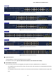
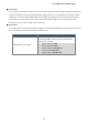
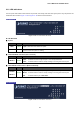
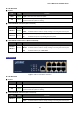
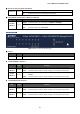
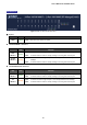
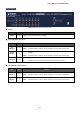
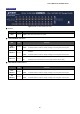
Table Of Contents
- 1. INTRODUCTION
- 2. INSTALLATION
- 3. SWITCH MANAGEMENT
- 4. WEB CONFIGURATION
- 4.1 Main Web Page
- 4.2 System
- 4.3 Switching
- 4.3.1 Port Management
- 4.3.1.1 Port Configuration
- 4.3.1.2 Port Counters
- 4.3.1.3 Bandwidth Utilization
- 4.3.1.4 Port Mirroring
- 4.3.1.5 Jumbo Frame
- 4.3.1.6 Port Error Disabled Configuration
- 4.3.1.7 Port Error Disabled Status
- 4.3.1.8 Protected Ports
- 4.3.1.9 EEE
- 4.3.2 Link Aggregation
- 4.3.2.1 LAG Setting
- 4.3.2.2 LAG Management
- 4.3.2.3 LAG Port Setting
- 4.3.2.4 LACP Setting
- 4.3.2.5 LACP Port Setting
- 4.3.2.6 LAG Status
- 4.3.3 VLAN
- 4.3.3.1 VLAN Overview
- 4.3.3.2 IEEE 802.1Q VLAN
- 4.3.3.3 Management VLAN
- 4.3.3.4 Create VLAN
- 4.3.3.5 Interface Settings
- 4.3.3.6 Port to VLAN
- 4.3.3.7 Port VLAN Membership
- 4.3.3.8 Protocol VLAN Group Setting
- 4.3.3.9 Protocol VLAN Port Setting
- 4.3.3.10 GVRP Setting
- 4.3.3.11 GVRP Port Setting
- 4.3.3.12 GVRP VLAN
- 4.3.3.13 GVRP Statistics
- 4.3.3.14 VLAN setting example:
- 4.3.3.14.1 Two separate 802.1Q VLANs
- 4.3.3.14.2 VLAN Trunking between two 802.1Q aware switches
- 4.3.4 Spanning Tree Protocol
- 4.3.5 Multicast
- 4.3.6 IGMP Snooping
- 4.3.7 MLD Snooping
- 4.3.8 LLDP
- 4.3.9 MAC Address Table
- 4.3.1 Port Management
- 4.4 Quality of Service
- 4.5 Security
- 4.6 Ring
- 4.7 Power over Ethernet
- 4.8 Maintenance
- 5. COMMAND LINE INTERFACE
- 6. Command Line Mode
- 6.1 User Mode Commands
- 6.2 Privileged Mode Commands
- 6.2.1 clear command
- 6.2.2 clock command
- 6.2.3 configure command
- 6.2.4 copy command
- 6.2.5 delete command
- 6.2.6 disable command
- 6.2.7 end command
- 6.2.8 exit command
- 6.2.9 ping command
- 6.2.10 reboot command
- 6.2.11 renew command
- 6.2.12 restore-defaults command
- 6.2.13 save command
- 6.2.14 show command
- 6.2.15 ssl command
- 6.2.16 terminal command
- 6.3 Global Config Mode Commands
- 6.3.1 aaa Command
- 6.3.2 boot Command
- 6.3.3 clock Command
- 6.3.4 dos Command
- 6.3.5 dot1x Command
- 6.3.6 do Command
- 6.3.7 enable Command
- 6.3.8 end Command
- 6.3.9 erps Command
- 6.3.10 errdisable Command
- 6.3.11 exit Command
- 6.3.12 gvrp Command
- 6.3.13 hostname Command
- 6.3.14 interface Command
- 6.3.15 ip Command
- 6.3.16 ipv6 Command
- 6.3.17 jumbo-frame Command
- 6.3.18 lacp Command
- 6.3.19 lag Command
- 6.3.20 line Command
- 6.3.21 lldp Command
- 6.3.22 logging Command
- 6.3.23 mac Command
- 6.3.24 management Command
- 6.3.25 management-vlan Command
- 6.3.26 mirror Command
- 6.3.27 nms Command
- 6.3.28 no Command
- 6.3.29 poe Command
- 6.3.30 port-security Command
- 6.3.31 qos Command
- 6.3.32 radius Command
- 6.3.33 rmon Command
- 6.3.34 Snmp Command
- 6.3.35 sntp Command
- 6.3.36 spanning-tree Command
- 6.3.37 storm-control Command
- 6.3.38 system Command
- 6.3.39 tacacs Command
- 6.3.40 username Command
- 6.3.41 vlan Command
- 6.3.42 voice-vlan Command
- 7. SWITCH OPERATION
- 8. POWER OVER ETHERNET OVERVIEW
- 9. TROUBLESHOOTING
- APPENDIX A

User’s Manual of GS-4210 Series
34
LED Definition
■ System
LED Color Function
PWR Green
Lights
to indicate that the Switch has power.
SYS Green
Off to indicate the system is booting.
Lights to indicate the system is working.
■ 10/100/1000BASE-T Interfaces (Port-1 to Port-8)
LED Color Function
LNK/ACT Green
Lights: To indicate the link through that port is successfully established.
Blinks: To indicate that the switch is actively sending or receiving data over that port.
PoE-In-Use Orange
Lights: To indicate the port is providing DC in-line power.
Off: To indicate the port is not providing DC in-line power.
■ 100/1000BASE-X SFP Interfaces (Port-9 to Port-10)
LED Color Function
100/1000
LNK/ACT
Green
Lights:
To indicate that the port is operating at 100Mbps or 1000Mbps.
Blinks:
Off:
To indicate that the switch is actively sending or receiving data over that port.
To indicate that the port is link down.
LED Indication
Figure 2-1-13: GS-4210-8P2C LED Panel
LED Definition
■ System
LED Color Function
PWR Green
Lights
to indicate that the Switch has power.
SYS Green
Off
to indicate the system is booting.
Lights
to indicate the system is working.
■ 10/100/1000BASE-T Interfaces (Port-1 to Port-10)
LED Color Function
LNK/ACT Green
Lights: To indicate the link through that port is successfully established.
Blinks: To indicate that the switch is actively sending or receiving data over that port.