
GS-4210-Series (V2) User Manual
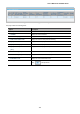
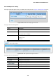
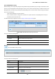
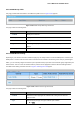
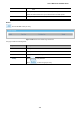
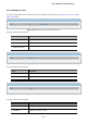
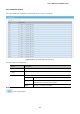
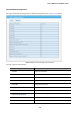

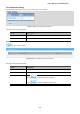
Table Of Contents
- 1. INTRODUCTION
- 2. INSTALLATION
- 3. SWITCH MANAGEMENT
- 4. WEB CONFIGURATION
- 4.1 Main Web Page
- 4.2 System
- 4.3 Switching
- 4.3.1 Port Management
- 4.3.1.1 Port Configuration
- 4.3.1.2 Port Counters
- 4.3.1.3 Bandwidth Utilization
- 4.3.1.4 Port Mirroring
- 4.3.1.5 Jumbo Frame
- 4.3.1.6 Port Error Disabled Configuration
- 4.3.1.7 Port Error Disabled Status
- 4.3.1.8 Protected Ports
- 4.3.1.9 EEE
- 4.3.2 Link Aggregation
- 4.3.2.1 LAG Setting
- 4.3.2.2 LAG Management
- 4.3.2.3 LAG Port Setting
- 4.3.2.4 LACP Setting
- 4.3.2.5 LACP Port Setting
- 4.3.2.6 LAG Status
- 4.3.3 VLAN
- 4.3.3.1 VLAN Overview
- 4.3.3.2 IEEE 802.1Q VLAN
- 4.3.3.3 Management VLAN
- 4.3.3.4 Create VLAN
- 4.3.3.5 Interface Settings
- 4.3.3.6 Port to VLAN
- 4.3.3.7 Port VLAN Membership
- 4.3.3.8 Protocol VLAN Group Setting
- 4.3.3.9 Protocol VLAN Port Setting
- 4.3.3.10 GVRP Setting
- 4.3.3.11 GVRP Port Setting
- 4.3.3.12 GVRP VLAN
- 4.3.3.13 GVRP Statistics
- 4.3.3.14 VLAN setting example:
- 4.3.3.14.1 Two separate 802.1Q VLANs
- 4.3.3.14.2 VLAN Trunking between two 802.1Q aware switches
- 4.3.4 Spanning Tree Protocol
- 4.3.5 Multicast
- 4.3.6 IGMP Snooping
- 4.3.7 MLD Snooping
- 4.3.8 LLDP
- 4.3.9 MAC Address Table
- 4.3.1 Port Management
- 4.4 Quality of Service
- 4.5 Security
- 4.6 Ring
- 4.7 Power over Ethernet
- 4.8 Maintenance
- 5. COMMAND LINE INTERFACE
- 6. Command Line Mode
- 6.1 User Mode Commands
- 6.2 Privileged Mode Commands
- 6.2.1 clear command
- 6.2.2 clock command
- 6.2.3 configure command
- 6.2.4 copy command
- 6.2.5 delete command
- 6.2.6 disable command
- 6.2.7 end command
- 6.2.8 exit command
- 6.2.9 ping command
- 6.2.10 reboot command
- 6.2.11 renew command
- 6.2.12 restore-defaults command
- 6.2.13 save command
- 6.2.14 show command
- 6.2.15 ssl command
- 6.2.16 terminal command
- 6.3 Global Config Mode Commands
- 6.3.1 aaa Command
- 6.3.2 boot Command
- 6.3.3 clock Command
- 6.3.4 dos Command
- 6.3.5 dot1x Command
- 6.3.6 do Command
- 6.3.7 enable Command
- 6.3.8 end Command
- 6.3.9 erps Command
- 6.3.10 errdisable Command
- 6.3.11 exit Command
- 6.3.12 gvrp Command
- 6.3.13 hostname Command
- 6.3.14 interface Command
- 6.3.15 ip Command
- 6.3.16 ipv6 Command
- 6.3.17 jumbo-frame Command
- 6.3.18 lacp Command
- 6.3.19 lag Command
- 6.3.20 line Command
- 6.3.21 lldp Command
- 6.3.22 logging Command
- 6.3.23 mac Command
- 6.3.24 management Command
- 6.3.25 management-vlan Command
- 6.3.26 mirror Command
- 6.3.27 nms Command
- 6.3.28 no Command
- 6.3.29 poe Command
- 6.3.30 port-security Command
- 6.3.31 qos Command
- 6.3.32 radius Command
- 6.3.33 rmon Command
- 6.3.34 Snmp Command
- 6.3.35 sntp Command
- 6.3.36 spanning-tree Command
- 6.3.37 storm-control Command
- 6.3.38 system Command
- 6.3.39 tacacs Command
- 6.3.40 username Command
- 6.3.41 vlan Command
- 6.3.42 voice-vlan Command
- 7. SWITCH OPERATION
- 8. POWER OVER ETHERNET OVERVIEW
- 9. TROUBLESHOOTING
- APPENDIX A

User’s Manual of GS-4210 Series
194
4.3.6.4 IGMP Group Table
This page provides Multicast Database. The IGMP Group Table screen in Figure 4-3-84 appears.
Figure 4-3-84: IGMP Group Table Page Screenshot
The page includes the following fields:
Object Description
• VLAN ID
Display the current VID.
• Group IP Address
Display multicast IP address for a specific multicast service.
• Member Port
Display the current member port.
• Type
Member types displayed include Static or Dynamic, depending on selected
options.
• Life(Sec)
Display the current life.
4.3.6.5 IGMP Router Setting
Depending on your network connections, IGMP snooping may not always be able to locate the IGMP querier. Therefore, if the
IGMP querier is a known multicast router/ switch connected over the network to an interface (port or trunk) on your Managed
Switch, you can manually configure the interface (and a specified VLAN) to join all the current multicast groups supported by the
attached router. This can ensure that multicast traffic is passed to all the appropriate interfaces within the Managed Switch.
The IGMP Router Setting and Status screens in Figure 4-3-85 & Figure 4-3-86 appear.
Figure 4-3-85: Add Router Port Page Screenshot
The page includes the following fields:
Object Description
• VLAN ID
Selects the VLAN to propagate all multicast traffic coming from the attached
multicast router.
• Type
Sets the Router port type. The types of Router port as below:
Static