
GS-4210-Series (V2) User Manual
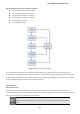
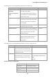
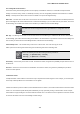
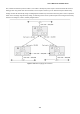
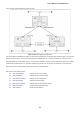
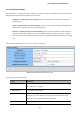
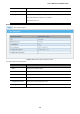
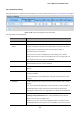
Table Of Contents
- 1. INTRODUCTION
- 2. INSTALLATION
- 3. SWITCH MANAGEMENT
- 4. WEB CONFIGURATION
- 4.1 Main Web Page
- 4.2 System
- 4.3 Switching
- 4.3.1 Port Management
- 4.3.1.1 Port Configuration
- 4.3.1.2 Port Counters
- 4.3.1.3 Bandwidth Utilization
- 4.3.1.4 Port Mirroring
- 4.3.1.5 Jumbo Frame
- 4.3.1.6 Port Error Disabled Configuration
- 4.3.1.7 Port Error Disabled Status
- 4.3.1.8 Protected Ports
- 4.3.1.9 EEE
- 4.3.2 Link Aggregation
- 4.3.2.1 LAG Setting
- 4.3.2.2 LAG Management
- 4.3.2.3 LAG Port Setting
- 4.3.2.4 LACP Setting
- 4.3.2.5 LACP Port Setting
- 4.3.2.6 LAG Status
- 4.3.3 VLAN
- 4.3.3.1 VLAN Overview
- 4.3.3.2 IEEE 802.1Q VLAN
- 4.3.3.3 Management VLAN
- 4.3.3.4 Create VLAN
- 4.3.3.5 Interface Settings
- 4.3.3.6 Port to VLAN
- 4.3.3.7 Port VLAN Membership
- 4.3.3.8 Protocol VLAN Group Setting
- 4.3.3.9 Protocol VLAN Port Setting
- 4.3.3.10 GVRP Setting
- 4.3.3.11 GVRP Port Setting
- 4.3.3.12 GVRP VLAN
- 4.3.3.13 GVRP Statistics
- 4.3.3.14 VLAN setting example:
- 4.3.3.14.1 Two separate 802.1Q VLANs
- 4.3.3.14.2 VLAN Trunking between two 802.1Q aware switches
- 4.3.4 Spanning Tree Protocol
- 4.3.5 Multicast
- 4.3.6 IGMP Snooping
- 4.3.7 MLD Snooping
- 4.3.8 LLDP
- 4.3.9 MAC Address Table
- 4.3.1 Port Management
- 4.4 Quality of Service
- 4.5 Security
- 4.6 Ring
- 4.7 Power over Ethernet
- 4.8 Maintenance
- 5. COMMAND LINE INTERFACE
- 6. Command Line Mode
- 6.1 User Mode Commands
- 6.2 Privileged Mode Commands
- 6.2.1 clear command
- 6.2.2 clock command
- 6.2.3 configure command
- 6.2.4 copy command
- 6.2.5 delete command
- 6.2.6 disable command
- 6.2.7 end command
- 6.2.8 exit command
- 6.2.9 ping command
- 6.2.10 reboot command
- 6.2.11 renew command
- 6.2.12 restore-defaults command
- 6.2.13 save command
- 6.2.14 show command
- 6.2.15 ssl command
- 6.2.16 terminal command
- 6.3 Global Config Mode Commands
- 6.3.1 aaa Command
- 6.3.2 boot Command
- 6.3.3 clock Command
- 6.3.4 dos Command
- 6.3.5 dot1x Command
- 6.3.6 do Command
- 6.3.7 enable Command
- 6.3.8 end Command
- 6.3.9 erps Command
- 6.3.10 errdisable Command
- 6.3.11 exit Command
- 6.3.12 gvrp Command
- 6.3.13 hostname Command
- 6.3.14 interface Command
- 6.3.15 ip Command
- 6.3.16 ipv6 Command
- 6.3.17 jumbo-frame Command
- 6.3.18 lacp Command
- 6.3.19 lag Command
- 6.3.20 line Command
- 6.3.21 lldp Command
- 6.3.22 logging Command
- 6.3.23 mac Command
- 6.3.24 management Command
- 6.3.25 management-vlan Command
- 6.3.26 mirror Command
- 6.3.27 nms Command
- 6.3.28 no Command
- 6.3.29 poe Command
- 6.3.30 port-security Command
- 6.3.31 qos Command
- 6.3.32 radius Command
- 6.3.33 rmon Command
- 6.3.34 Snmp Command
- 6.3.35 sntp Command
- 6.3.36 spanning-tree Command
- 6.3.37 storm-control Command
- 6.3.38 system Command
- 6.3.39 tacacs Command
- 6.3.40 username Command
- 6.3.41 vlan Command
- 6.3.42 voice-vlan Command
- 7. SWITCH OPERATION
- 8. POWER OVER ETHERNET OVERVIEW
- 9. TROUBLESHOOTING
- APPENDIX A

User’s Manual of GS-4210 Series
164
User-Changeable STA Parameters
The Switch’s factory default setting should cover the majority of installations. However, it is advisable to keep the default
settings as set at the factory; unless, it is absolutely necessary. The user changeable parameters in the Switch are as follows:
Priority – A Priority for the switch can be set from 0 to 65535. 0 is equal to the highest Priority.
Hello Time – The Hello Time can be from 1 to 10 seconds. This is the interval between two transmissions of BPDU packets sent
by the Root Bridge to tell all other Switches that it is indeed the Root Bridge. If you set a Hello Time for your Switch, and it is not
the Root Bridge, the set Hello Time will be used if and when your Switch becomes the Root Bridge.
The Hello Time cannot be longer than the Max. Age. Otherwise, a configuration error will
occur.
Max. Age – The Max Age can be from 6 to 40 seconds. At the end of the Max Age, if a BPDU has still not been received from
the Root Bridge, your Switch will start sending its own BPDU to all other Switches for permission to become the Root Bridge. If it
turns out that your Switch has the lowest Bridge Identifier, it will become the Root Bridge.
Forward Delay Timer – The Forward Delay can be from 4 to 30 seconds. This is the time any port on the
Switch spends in the listening state while moving from the blocking state to the forwarding state.
Observe the following formulas when setting the above parameters:
Max. Age _ 2 x (Forward Delay - 1 second)
Max. Age _ 2 x (Hello Time + 1 second)
Port Priority – A Port Priority can be from 0 to 240. The lower the number, the greater the probability the port will be chosen as
the Root Port.
Port Cost – A Port Cost can be set from 0 to 200000000. The lower the number, the greater the probability the port will be
chosen to forward packets.
3. Illustration of STP
A simple illustration of three switches connected in a loop is depicted in the below diagram. In this example, you can anticipate
some major network problems if the STP assistance is not applied.
If switch A broadcasts a packet to switch B, switch B will broadcast it to switch C, and switch C will broadcast it to back to switch
A and so on. The broadcast packet will be passed indefinitely in a loop, potentially causing a network failure. In this example,
STP breaks the loop by blocking the connection between switch B and C. The decision to block a particular connection is based
on the STP calculation of the most current Bridge and Port settings.