
GS-4210-Series (V2) User Manual
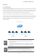
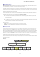
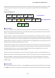
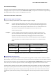
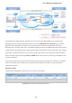
Table Of Contents
- 1. INTRODUCTION
- 2. INSTALLATION
- 3. SWITCH MANAGEMENT
- 4. WEB CONFIGURATION
- 4.1 Main Web Page
- 4.2 System
- 4.3 Switching
- 4.3.1 Port Management
- 4.3.1.1 Port Configuration
- 4.3.1.2 Port Counters
- 4.3.1.3 Bandwidth Utilization
- 4.3.1.4 Port Mirroring
- 4.3.1.5 Jumbo Frame
- 4.3.1.6 Port Error Disabled Configuration
- 4.3.1.7 Port Error Disabled Status
- 4.3.1.8 Protected Ports
- 4.3.1.9 EEE
- 4.3.2 Link Aggregation
- 4.3.2.1 LAG Setting
- 4.3.2.2 LAG Management
- 4.3.2.3 LAG Port Setting
- 4.3.2.4 LACP Setting
- 4.3.2.5 LACP Port Setting
- 4.3.2.6 LAG Status
- 4.3.3 VLAN
- 4.3.3.1 VLAN Overview
- 4.3.3.2 IEEE 802.1Q VLAN
- 4.3.3.3 Management VLAN
- 4.3.3.4 Create VLAN
- 4.3.3.5 Interface Settings
- 4.3.3.6 Port to VLAN
- 4.3.3.7 Port VLAN Membership
- 4.3.3.8 Protocol VLAN Group Setting
- 4.3.3.9 Protocol VLAN Port Setting
- 4.3.3.10 GVRP Setting
- 4.3.3.11 GVRP Port Setting
- 4.3.3.12 GVRP VLAN
- 4.3.3.13 GVRP Statistics
- 4.3.3.14 VLAN setting example:
- 4.3.3.14.1 Two separate 802.1Q VLANs
- 4.3.3.14.2 VLAN Trunking between two 802.1Q aware switches
- 4.3.4 Spanning Tree Protocol
- 4.3.5 Multicast
- 4.3.6 IGMP Snooping
- 4.3.7 MLD Snooping
- 4.3.8 LLDP
- 4.3.9 MAC Address Table
- 4.3.1 Port Management
- 4.4 Quality of Service
- 4.5 Security
- 4.6 Ring
- 4.7 Power over Ethernet
- 4.8 Maintenance
- 5. COMMAND LINE INTERFACE
- 6. Command Line Mode
- 6.1 User Mode Commands
- 6.2 Privileged Mode Commands
- 6.2.1 clear command
- 6.2.2 clock command
- 6.2.3 configure command
- 6.2.4 copy command
- 6.2.5 delete command
- 6.2.6 disable command
- 6.2.7 end command
- 6.2.8 exit command
- 6.2.9 ping command
- 6.2.10 reboot command
- 6.2.11 renew command
- 6.2.12 restore-defaults command
- 6.2.13 save command
- 6.2.14 show command
- 6.2.15 ssl command
- 6.2.16 terminal command
- 6.3 Global Config Mode Commands
- 6.3.1 aaa Command
- 6.3.2 boot Command
- 6.3.3 clock Command
- 6.3.4 dos Command
- 6.3.5 dot1x Command
- 6.3.6 do Command
- 6.3.7 enable Command
- 6.3.8 end Command
- 6.3.9 erps Command
- 6.3.10 errdisable Command
- 6.3.11 exit Command
- 6.3.12 gvrp Command
- 6.3.13 hostname Command
- 6.3.14 interface Command
- 6.3.15 ip Command
- 6.3.16 ipv6 Command
- 6.3.17 jumbo-frame Command
- 6.3.18 lacp Command
- 6.3.19 lag Command
- 6.3.20 line Command
- 6.3.21 lldp Command
- 6.3.22 logging Command
- 6.3.23 mac Command
- 6.3.24 management Command
- 6.3.25 management-vlan Command
- 6.3.26 mirror Command
- 6.3.27 nms Command
- 6.3.28 no Command
- 6.3.29 poe Command
- 6.3.30 port-security Command
- 6.3.31 qos Command
- 6.3.32 radius Command
- 6.3.33 rmon Command
- 6.3.34 Snmp Command
- 6.3.35 sntp Command
- 6.3.36 spanning-tree Command
- 6.3.37 storm-control Command
- 6.3.38 system Command
- 6.3.39 tacacs Command
- 6.3.40 username Command
- 6.3.41 vlan Command
- 6.3.42 voice-vlan Command
- 7. SWITCH OPERATION
- 8. POWER OVER ETHERNET OVERVIEW
- 9. TROUBLESHOOTING
- APPENDIX A

User’s Manual of GS-4210 Series
134
■ IEEE 802.1Q Standard
IEEE 802.1Q (tagged) VLAN are implemented on the Switch. 802.1Q VLAN require tagging, which enables them to span the
entire network (assuming all switches on the network are IEEE 802.1Q-compliant).
VLAN allow a network to be segmented in order to reduce the size of broadcast domains. All packets entering a VLAN will only
be forwarded to the stations (over IEEE 802.1Q enabled switches) that are members of that VLAN, and this includes broadcast,
multicast and unicast packets from unknown sources.
VLAN can also provide a level of security to your network. IEEE 802.1Q VLAN will only deliver packets between stations that
are members of the VLAN. Any port can be configured as either tagging or untagging.:
The untagging feature of IEEE 802.1Q VLAN allows VLAN to work with legacy switches that don't recognize VLAN
tags in packet headers.
The tagging feature allows VLAN to span multiple 802.1Q-compliant switches through a single physical connection and
allows Spanning Tree to be enabled on all ports and work normally.
Some relevant terms:
- Tagging - The act of putting 802.1Q VLAN information into the header of a packet.
- Untagging - The act of stripping 802.1Q VLAN information out of the packet header.
■ 802.1Q VLAN Tags
The figure below shows the 802.1Q VLAN tag. There are four additional octets inserted after the source MAC address. Their
presence is indicated by a value of 0x8100 in the Ether Type field. When a packet's Ether Type field is equal to 0x8100, the
packet carries the IEEE 802.1Q/802.1p tag. The tag is contained in the following two octets and consists of 3 bits of user priority,
1 bit of Canonical Format Identifier (CFI - used for encapsulating Token Ring packets so they can be carried across Ethernet
backbones), and 12 bits of VLAN ID (VID). The 3 bits of user priority are used by 802.1p. The VID is the VLAN identifier and is
used by the 802.1Q standard. Because the VID is 12 bits long, 4094 unique VLAN can be identified.
The tag is inserted into the packet header making the entire packet longer by 4 octets. All of the information originally contained
in the packet is retained.
802.1Q Tag
User Priority CFI VLAN ID (VID)
3 bits 1 bits 12 bits
TPID (Tag Protocol Identifier) TCI (Tag Control Information)
2 bytes 2 bytes
Preamble
Destination
Address
Source
Address
VLAN TAG
Ethernet
Type
Data FCS
6 bytes 6 bytes 4 bytes 2 bytes 46-1500 bytes 4 bytes