PLANET 5/8/16-Port 10/100Mbps SOHO Fast Ethernet Switch FSD-503 / FSD-803 / FSD-1603 User's Manual
Trademarks Copyright © PLANET Technology Corp. 2007. Contents subject to revision without prior notice. PLANET is a registered trademark of PLANET Technology Corp. All other trademarks belong to their respective owners. Disclaimer PLANET Technology does not warrant that the hardware will work properly in all environments and applications, and makes no warranty and representation, either implied or expressed, with respect to the quality, performance, merchantability, or fitness for a particular purpose.
CE Mark Warning This is a Class B product. In a domestic environment, this product may cause radio interference, in which case the user may be required to take adequate measures. WEEE Warning To avoid the potential effects on the environment and human health as a result of the presence of hazardous substances in electrical and electronic equipment, end users of electrical and electronic equipment should understand the meaning of the crossed-out wheeled bin symbol.
TABLE OF CONTENTS 1. Introduction................................................................................................ 5 1.1 Package Contents.................................................................................. 5 1.2 How to Use This Manual . ...................................................................... 5 1.3 Product Features.................................................................................... 5 1.4 Product Specifications........................................
1. Introduction 1.1 Package Contents Check the contents of your package for following parts: ● Fast Ethernet Switch x 1 ● User's manual x 1 ● Power adapter x 1 ● Rubber feet x 4 If any of these are missing or damaged, please contact your dealer immediately, if possible, retain the carton including the original packing material, and use them against to repack the product in case there is a need to return it to us for repair. 1.
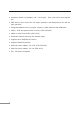
● Hardware based 10/100Mbps, half / full duplex , flow control and auto-negotiation ● IEEE 802.3x flow control for full duplex operation and Backpressure for half duplex operation ● Integrated address look-up engine, support 1/2/8K absolute MAC addresses ● 384K / 512K bits packet buffer memory (FSD-503/803) ● 4Mbit on-chip frame buffer (FSD-1603) ● Automatic address learning and address aging ● Supports Auto MDI/MDI-X function ● Support CSMA/CD protocol ● External power adapter 12V 0.
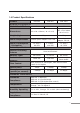
1.4 Product Specifications Product FSD-503 FSD-803 FSD-1603 5 8 16 Hardware Specification 10/100Base-TX Ports Dimensions 160 x 80 x 28mm ( W x D x H) Weight (kg) Power Requirement 325g 850g External power adapter 12V 0.5A Power Consumption / Dissipation Switch Specification Switch Processing Scheme Address Table Packet buffer memory Flow Control 267 x 79 x 26mm (W x D x H) 2.6 watts / 8.8 BTU External power adapter 12V 1A 4.3 watts / 14.6 BTU 5.5 watts / 18.
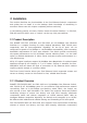
2. Installation This section describes the functionalities of the Fast Ethernet Switch’s components and guides how to install it on the desktop. Basic knowledge of networking is assumed. Please read this chapter completely before continuing. In the following section, the term “Switch” means the three Switches, i.e. FSD-503, FSD-803 and FSD-1603; term of “switch” can be any third part switches. 2.
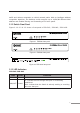
traffic and relieves congestion on critical network paths. With an intelligent address recognition algorithm, the Switches could recognize up to 1K/2K/8K different MAC address and enables filtering and forwarding at full wire speed. 2.1.2 Switch Front Panel Figure 2-1 & 2-2 & 2-3 shows a front panel of FSD-503 / FSD-803 / FSD-1603. Figure 2-1 FSD-503 front panel Figure 2-2 FSD-803 front panel Figure 2-3 FSD-1603 front panel 2.1.
FSD-1603 LED Color PWR Green Lit: Power on Green Lit: indicate that the port is operating at 100Mbps. Off: indicate that the port is operating at 10Mbps. Blink: indicate that the Switch is actively sending or receiving data over that port 10/100 Function 2.1.4 Switch Rear Panel Figure 2-4 & 2-5 & 2-6 shows a rear panel of FSD-503 / FSD-803 / FSD-1603. Figure 2-4 FSD-503 rear panel Figure 2-5 FSD-803 rear panel Figure 2-6 FSD-1603 rear panel Power Notice: 1.
2. In some area, installing a surge suppression device may also help to protect your Switch from being damaged by unregulated surge or current to the Switch or the power adapter. 2.2 Installing the Switch This part describes how to install your Fast Ethernet Switch and make connections to it. Please read the following topics and perform the procedures in the order being presented. Note This Switch does not need software configuration. 2.2.
Step 5: Supply power to the Switch. A. Connect one end of the power cable to the Switch. B. Connect the 12V DC power adapter to a standard wall outlet. When the Switch receives power, the Power LED should remain solid Green.
3. Switch Operation 3.1 Address Table The Switch is implemented with an address table. This address table composed of many entries. Each entry is used to store the address information of some node in network, including MAC address, port no, etc. This information comes from the learning process of Ethernet Switch. 3.2 Learning When one packet comes in from any port. The Switch will record the source address, port no. And the other related information in address table.
servers directly to the network, thereby increasing throughput and availability. However, the Switch is most commonly used to segment existing hubs, which nearly always improves overall performance. An Ethernet Switching can be easily configured in any Ethernet network environment to significantly boost bandwidth using conventional cabling and adapters.
4. Troubleshooting This chapter contains information to help you solve problems. If the Switch is not functioning properly, make sure the Fast Ethernet Switch was set up according to instructions in this manual. The per port LED is not lit Solution: Check the cable connection of the FSD-503 / FSD-803 / FSD-1603. Performance is bad Solution: Check the speed duplex mode of the partner device.
Appendix A Networking Connection A.1 Switch‘s RJ-45 Pin Assignments 10/100Mbps, 10/100Base-TX RJ-45 Connector pin assignment Contact MDI Media Dependant Interface MDI-X Media Dependant Interface -Cross 1 Tx + (transmit) Rx + (receive) 2 Tx - (transmit) Rx - (receive) 3 Rx + (receive) Tx + (transmit) 4, 5 6 7, 8 Not used Rx - (receive) Tx - (transmit) Not used A.
Figure A-1: Straight-Through and Crossover Cable Please make sure your connected cables are with same pin assignment and color as above picture before deploying the cables into your network.
This page is intentionally left blank
This page is intentionally left blank
This page is intentionally left blank