
User's Manual


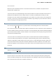

Table Of Contents
- 1. INTRODUCTION
- 2. INSTALLATION
- 3. SWITCH MANAGEMENT
- 4. WEB CONFIGURATION
- 4.1 Main Web Page
- 4.2 System
- 4.3 PoE Configuration
- 4.4 Basic Configuration
- 4.5 VLAN Configuration
- 4.6 QoS Configuration
- 4.7 ACL Configuration
- 4.8 Security
- 4.9 Advanced Features
- 4.10 Monitoring
- 5. COMMAND LINE INTERFACE
- 6. Command Line Mode
- 7. SWITCH OPERATION
- 8. Power over Ethernet Overview
- 9. TROUBLESHOOTING
- APPENDEX A: Networking Connection
- APPENDIX B: GLOSSARY

User’s Manual of WGSW-20160HP
The standard cable, RJ45 pin assignment
2 1 3 6
1
2
3
6
2 1
3 6
The standard RJ45 receptacle/connector
There are 8 wires on a standard UTP/STP cable and each wire is color-coded. The following shows the pin allocation
and color of straight cable and crossover cable connection:
Straight Cable
SIDE 1
SIDE2
SIDE 1
1 = White / Orange
2 = Orange
3 = White / Green
4 = Blue
5 = White / Blue
6 = Green
7 = White / Brown
8 = Brown
1 = White / Orange
2 = Orange
3 = White / Green
4 = Blue
5 = White / Blue
6 = Green
7 = White / Brown
8 = Brown
SIDE 2
Crossover Cable
SIDE 1
SIDE2
SIDE 1
1 = White / Orange
2 = Orange
3 = White / Green
4 = Blue
5 = White / Blue
6 = Green
7 = White / Brown
8 = Brown
1 = White / Green
2 = Green
3 = White / Orange
4 = Blue
5 = White / Blue
6 = Orange
7 = White / Brown
8 = Brown
SIDE 2
Figure A-1: Straight-through and Crossover Cable
Please make sure your connected cables are with same pin assignment and color as the above table before deploying
the cables into your network.
1 2 3 4 5 6 7 8
1 2 3 4 5 6 7 8
1 2 3 4 5 6 7 8
1 2 3 4 5 6 7 8