User's Manual FGSW-1820CS FGSW-2620CS 16/24-Port 10/100Mbps with 2 Gigabit TP / SFP Combo Web Smart Switch -1-
Trademarks Copyright © PLANET Technology Corp. 2008. Contents subject to revision without prior notice. PLANET is a registered trademark of PLANET Technology Corp. All other trademarks belong to their respective owners. Disclaimer PLANET Technology does not warrant that the hardware will work properly in all environments and applications, and makes no warranty and representation, either implied or expressed, with respect to the quality, performance, merchantability, or fitness for a particular purpose.
TABLE OF CONTENTS 1. INTRODUCTION ...................................................................................................................................................... 4 1.1 CHECKLIST................................................................................................................................................................ 4 1.2 ABOUT THE SWITCH ................................................................................................................................
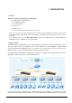
1. INTRODUCTION 1.
advanced switch management functions such as port configuration, port-based / IEEE 802.1Q / MTU VLAN, port mirroring, port trunk, QoS, bandwidth control, broadcast storm control, MAC address / TCP & UDP filter and IGMP Snooping v1/v2. The FGSW-1820CS / FGSW-2620CS provide port-based / IEEE 802.1Q / MTU VLAN (port based / IEEE 802.1Q VLAN including overlapping). The VLAN groups allowed on the FGSW-1820CS / FGSW-2620CS, will be maximally up to 18/26 for port-based / 32 for IEEE 802.1Q VLAN groups.
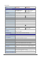
1.4 Specification Model FGSW-1820CS FGSW-2620CS Ports 16 10/ 100Base-TX RJ-45 Auto-MDI/MDI-X ports 24 10/ 100Base-TX RJ-45 Gigabit ports 2 10/100/1000Mbps ports share with 2 SFP interfaces Switch Processing Scheme Store-and-Forward Throughput (packet per second) 5.35Mpps. 6.54Mpps Switch Fabric 7.2Gbps. 8.8Gbps Address Table 4K entries Share Data Buffer 2.75Mb embedded memory for packet buffers Flow Control Back pressure for half duplex, IEEE 802.
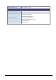
IGMP Snooping v1 / v2 Allow to disable or enable. Standards Conformance Regulation Compliance FCC Part 15 Class A, CE IEEE 802.3 (Ethernet) IEEE 802.3u (Fast Ethernet) IEEE 802.3ab(Gigabit Ethernet) Standards Compliance IEEE 802.3z(Gigabit Ethernet) IEEE 802.3x (Full-duplex flow control) IEEE 802.1Q VLAN IEEE 802.
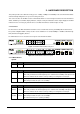
2. HARDWARE DESCRIPTION This product provides three different running speeds – 10Mbps, 100Mbps and 1000Mbps in the same Web Smart Switch and automatically distinguishes the speed of incoming connection. This section describes the hardware features of Web Smart Switch. For easier management and control of the Web Smart Switch, familiarize yourself with its display indicators, and ports. Front panel illustrations in this chapter display the unit LED indicators.
#Notice: 1. Press the RESET button once. The Web Smart Switch will reboot automatically. 2. Press the RESET button for 5 seconds. The Web Smart Switch will back to the factory default mode; the entire configuration will be erased. 2.2 Rear Panel The rear panel of the Web Smart Switch indicates an AC inlet power socket, which accepts input power from 100 to 240VAC, 50-60Hz, 0.5A. Figure 2-3: FGSW-1820C / FGSW-2620CS Switch rear panel Power Notice: 1.
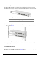
2.3.2 Rack Mounting To install the Web Smart Switch in a 19-inch standard rack, follow the instructions described below. Step 1: Place your Web Smart Switch on a hard flat surface, with the front panel positioned towards your front side. Step 2: Attach a rack-mount bracket to each side of the Web Smart Switch with supplied screws attached to the package. Figure 2-4 shows how to attach brackets to one side of the Web Smart Switch.
Figure 2-6 Plug-in the SFP transceiver Approved PLANET SFP Transceivers PLANET Web Smart Switch supports both single mode and multi mode SFP transceiver. The following list of approved PLANET SFP transceivers is correct at the time of publication: ■MGB-SX SFP (1000Base-SX SFP transceiver ) ■MGB-LX SFP (1000Base-LX SFP transceiver ) #Notice: It recommends using PLANET SFP transceiver on the Web Smart Switch. If you insert a SFP transceiver that is not supported, the Web Smart Switch will not recognize it.
Figure 2-7 Pull out the SFP transceiver #Notice: Never pull out the module without pull the handle or the push bolts on the module. Direct pull out the module with violent could damage the module and SFP module slot of the Web Smart Switch.
3. SWITCH MANAGEMENT This chapter describes how to manage the Web Smart Switch. Topics include: - Overview - Management method - Logging on to the Web Smart Switch 3.1 Overview The Web Smart Switch provides a user-friendly, Web interface. Using this interface, you can perform various switch configuration and management activities, including: Please refer to the following Chapter 4 for the details. 3.2 Management Method User can manage the Web Smart Switch by Web Management via a network connection. 3.2.
Figure 3-1 Planet Smart Discovery Utility Screen #Notice: If there are two LAN cards or above in the same administrator PC, choose different LAN card by use the “Select Adapter” tool. 3. Press “Refresh” button for list current connected devices in the discovery list, the screen is shown as follow. Figure 3-2 Planet Smart Discovery Utility Screen 3.
5. To click the “Control Packet Force Broadcast” function, it can allow assign new setting value to the Web Smart Switch under different IP subnet address. 6. Press “Connect to Device” button then the Web login screen appears in Figure 3-3. 7. Press “Exit” button to shutdown the planet Smart Discovery Utility. 3.
4. WEB MANAGEMENT To modify your PC’s IP domain to the same with Web Smart Switch then use the default IP address (192.168.0.100) to remote configure Web Smart Switch through the Web interface. #Notice: The following section will base on the console screens of FGSW-2620CS, for FGSW-1820CS the display will be the same to FGSW-2620CS. 4.1 Login in to the Switch To access the Web-browser interface you must first enter the user name and password, the default user name and password is "admin”.
The Switch Menu provide seven major management functions, the screen in Figure 4-2 appears. Figure 4-2 Web Main Menu Screen The seven items and it description shown as below: ◆ System: Provide System configuration of Web Smart Switch. Explained in section 4.2. ◆ Port Management: Provide Port Management configuration of Web Smart Switch. Explained in section 4.3. ◆ VLAN Setting: Provide VLAN Setting configuration of Web Smart Switch. Explained in section 4.4.
4.2 System This section provides System Information, IP Configuration, Password Setting, Factory Default, Firmware Update and Reboot functions of Web Smart Switch, the screen in Figure 4-3 appears and Table 4-1 describes the System object of Web Smart Switch. Figure 4-3 System Web Page Screen Object Description System Information Display the MAC address, Hardware Version, and Software Version, Device Description. Explained in section 4.2.1.
4.2.1 System Information This section displays the MAC address, Hardware Version and Software Version, also allow define the device description and press “Apply” button to take affect. The screen in Figure 4-4 appears. Figure 4-4 System Information Web Page Screen #Notice: Up to 16 characters is allowed for the Device Description.
4.2.2 IP Configuration This section provides change the IP Address, Subnet Mask and Gateway, the screen in Figure 4-5 appears. Figure 4-5 IP Configuration Web Page Screen .After setup complete and press “Apply” button to take affect. The following screen in Figure 4-6 appears and then another Web page login screen with new IP address will show up. After input correct username and password then can continue the Web Smart Switch management.
4.2.3 Password Setting This section provides change the Username and Password, the screen in Figure 4-7 appears. Figure 4-7 Password Setting Web Page Screen #Notice: Up to 8 characters is allowed for the username and password assign.
4.2.4 Factory Default This section provides reset the Web Smart Switch to factory default mode, the screen in Figure 4-8 appears. Figure 4-8 Factory Default Web Page Screen Press “Factory Default” button to take affect. The following screen in Figure 4-9 appears and then another Web page login screen with default setting will show up. After input default username and password then can continue the Web Smart Switch management.
4.2.5 Firmware Update This section provides firmware upgrade of the Web Smart Switch, the screen in Figure 4-10 appears. Figure 4-10 Firmware Update Web Page Screen Press “Update” button for start the firmware upgrade process, the screen in Figure 4-11 & 4-12 appears.
Figure 4-12 Firmware Update Web page Screen Then the following screen appears, press “Browser” button to find the firmware location administrator PC, the screen in Figure 4-13 appears.
After find the firmware location from administrator PC, press “Update” button to start the firmware upgrade process. The screen in Figure 4-14 appears. Figure 4-14 Firmware Update Web Page Screen When firmware upgrade process is completed then the following screen appears, please wait for a while for system reboot. After device reboot then can use the latest firmware of the Web Smart Switch. Figure 4-15 Firmware Update Web Page Screen #Notice: Recommend to use IE 6.
4.2.6 Reboot This section allows reboot the Web Smart Switch, the screen in Figure 4-16 appears. Figure 4-16 Reboot Web Page Screen Press “Reboot” button to reboot the Web Smart Switch, the screen in Figure 4-17 appears. After device reboot completed, the Web login screen appears and login for further management.
4.3 Port Management This section provides Port Configuration, Port Mirroring, Bandwidth Control, Broadcast Storm Control and Port Statistics from Web Smart Switch, the screen in Figure 4-18 appears and Table 4-2 describes the system object of Web Smart Switch. Figure 4-18 Port Management Web Page Screen Object Description Port Configuration Allow to configure each port of Web Smart Switch. Explained in section 4.3.1. Port Mirroring Allow to use port mirroring function of Web Smart Switch.
4.3.1 Port Configuration This section introduces detail settings of per port on Web Smart Switch; the screen in Figure 4-19 & 4-20 appears and Table 4-3 & 4-4 descriptions the Port Configuration objects of Web Smart Switch.
Object Port Description Port Description Allow choosing all or one port of Web Smart Switch for further management, the available options is All & 01 to 26 (FGSW-2620CS). Or All & 01 to 18 (FGSW-1820CS). Allow choosing various speed duplex mode from one specific port of Web Smart Switch, the available options are shown as below: Auto Negotiation 1000Full(1000Mbps Port Only) 100Full 100Half 10Full 10Half Default mode is Auto Negotiation.
4.3.2 Port Mirroring This section introduces detail settings of Port Mirroring function of Web Smart Switch; the screen in Figure 4-21 appears and Table 4-5 descriptions the Port Mirroring objects of Web Smart Switch. Figure 4-21 Port Mirroring Web Page Screen Object Description Monitored Packets Provide disable and enable the Port Mirroring function, the available options are Disable, RX, TX, TX & RX. Default mode is Disable.
4.3.3 Bandwidth Control This section introduces detail settings of Bandwidth Control function of Web Smart Switch; the screen in Figure 4-22 appears and Table 4-6 description the Bandwidth Control objects of Web Smart Switch.
4.3.4 Broadcast Storm Control This section introduces detail settings of Broadcast Storm Control function of Web Smart Switch; the screen in Figure 4-23 appears and Table 4-7 descriptions the Broadcast Storm Control objects of Web Smart Switch. Figure 4-23 Broadcast Storm Control Web Page Screen Object Description Filter Mode Provide 5%, 10%, 25%, 50%, Disable different filter mode. Default mode is Disable. Apply button Press this button for save current configuration of Web Smart Switch.
4.3.5 Port Statistics This section introduces detail information of Port Statistics function of Web Smart Switch; the screen in Figure 4-24 appears and Table 4-8 descriptions the Port Statistics objects of Web Smart Switch.
4.4 VLAN Setting A Virtual LAN (VLAN) is a logical network grouping that limits the broadcast domain. It allows you to isolate network traffic so only members of the VLAN receive traffic from the same VLAN members. Basically, creating a VLAN from a switch is logically equivalent of reconnecting a group of network devices to another Layer 2 switch. However, all the network devices are still plug into the same switch physically. The Switch supports IEEE 802.
802.1Q Tag User Priority 3 bits TPID (Tag Protocol Identifier) Destination Address Source Address 6 bytes 12 bits TCI (Tag Control Information) 2 bytes Ethernet Type VLAN TAG 6 bytes VLAN ID (VID) 1 bits 2 bytes Preamble CFI 4 bytes 2 bytes Data FCS 46-1517 bytes 4 bytes The Ether Type and VLAN ID are inserted after the MAC source address, but before the original Ether Type/Length or Logical Link Control.
VLAN Settings This section provides VLAN Configuration from Web Smart Switch, the screen in Figure 4-25 appears and Table 4-9 describes the VLAN Configuration object of Web Smart Switch. Figure 4-25 VLAN Setting Web Page Screen Object VLAN Mode Apply button Description Provide different VLAN operation mode, the available options are shown as below: No VLAN Port Based VLAN. Explained in section 4.4.1. 802.1Q VLAN. Explained in section 4.4.3. MTU. Explained in section 4.4.5. Default mode is No VLAN.
4.4.1 Port Based VLAN This section introduces detail information of Port Based VLAN function of Web Smart Switch; Choose “Port Based VLAN” from VLAN from the VLAN Mode and press “Apply” button to enable the port based VLAN function. The screen in Figure 4-26 & 4-27 & 4-28 appears and Table 4-10 description the Port Based VLAN objects of Web Smart Switch.
Figure 4-28 Port Based VLAN Configuration Web Page Screen Object Description VID Display different VLAN ID from multi-port based VLAN groups. VLAN Name Port Assign and display different VLAN name from multi-port based VLAN groups. Up to maximum 8 characters allow. Indicate port 1 to port 26 (FGSW-2620CS), port 1 to port 18 (FGSW-1820CS). Member Allow to click specific port as member port from different port based VLAN groups.
After the above steps port 1 to port 25 is being separated physically due to it belongs to different VLAN groups (different VLAN). However, they all can access port 26 due to port 26 is using overlapping feature to communicate with port 1 to port 25. 4.4.3 802.1Q VLAN This section introduces detail information of IEEE 802.1Q VLAN function of Web Smart Switch; Choose “802.1Q VLAN” from VLAN from the VLAN Mode and press “Apply” button to enable the 802.1Q VLAN function.
Figure 4-31 802.1Q VLAN Configuration Web Page Screen Object Description Group Display the existence 802.1Q VLAN groups. VID Display different VLAN ID from multi-802.1Q VLAN groups. VLAN Name Port Assign and display different VLAN name from multi-802.1Q VLAN groups. Up to maximum 8 characters allow. Indicate port 1 to port 26 (FGSW-2620CS), port 1 to port 18 (FGSW-1820CS). Member Allow to click specific port as member port from different 802.1Q VLAN groups.
Figure 4-32 802.1Q VLAN Per Port Setting Web Page Screen This section introduces detail information of IEEE 802.1Q VLAN Per Port Setting of Web Smart Switch; The Table 4-12 description the 802.1Q VLAN Per Port Setting objects of Web Smart Switch. Object Description Port Indicate port 1 to port 26 (FGSW-2620CS), port 1 to port 18 (FGSW-1820CS). Link Type Define UnTag or Tag on each port of Web Smart Switch. Default mode is “UnTag”. Uplink Define No Uplink or Uplink on each port of Web Smart Switch.
4.4.4 802.1Q VLAN Setting example Two separate 802.1Q VLAN scenario 1. Shows how the Web Smart Switch handles Untagged and Tagged traffic from two 802.1Q VLAN groups. 2. Each VLAN isolate network traffic, only the same VLAN member port can receive traffic from each other. Figure 4-33 two separate 802.
Setup steps 1. Create VLAN Group: Set VLAN Group 1 = default-VLAN with VID (VLAN ID) =1. Add two VLANs – VLAN 2 and VLAN 3, VLAN Group 2 with VID=2, VLAN Group 3 with VID=3. Figure 4-34 Add new VLAN Group Screen 2. Assign VLAN Member : VLAN 2 : Port-1,Port-2 and Port-3. VLAN 3 : Port-4, Port-5 and Port-6. VLAN 1: All other ports – Port-7~Port-24.
Please remember to remove the Port 1 – Port 6 from VLAN 1 membership, since the Port 1 – Port 6 had been assigned to VLAN 2 and VLAN 3. Figure 4-36 Remove specify ports from VLAN 1 member #Notice: Its import to remove the VLAN member port from VLAN 1 group. Or the ports would become overlapping setting.
3. Assign PVID for each port: Port-1,Port-2 and Port-3 : PVID=2. Port-4,Port-5 and Port-6 : PVID=3. Port-7~Port-24 : PVID=1. 4. Enable VLAN Tag for specific ports Link Type: Port-3 (VLAN-2) and Port-6 (VLAN-3). The Per Port VLAN configuration in Figure 4-37 appears. Figure 4-37 Port 1-Port 6 802.1Q VLAN Configuration Two separate 802.1Q VLAN with overlapping area scenario 1. Based on the two separate VLAN group examples above, VLAN 2 and VLAN 3 member port cannot see each other. 2.
2. Assign Port-7 to both VLAN 2 and VLAN 3 at the VLAN Member configuration page. The screen in Figure 4-39 appears. Figure 4-39 VLAN overlap port setting 3. Define a VLAN 1 as a “Public Area” that overlapping with both VLAN 2 members and VLAN 3 members.
4. Setup Port-7 with “PVID=1” at VLAN Per Port Configuration page. The screen in Figure 4-41 appears. Figure 4-41 Setup Port-7 with PVID-1 Although the VLAN 2 members: Port-1 to Port-3 and VLAN 3 members: Port-4 to Port-6 also belongs to VLAN 1. But with different PVID settings, packets form VLAN 2 or VLAN 3 is not able to access to the other VLAN.
4.4.5 MTU VLAN This section introduces detail information of MTU VLAN function of Web Smart Switch; Choose “MTU” from VLAN from the VLAN Mode and press “Apply” button to enable the MTU VLAN function. The screen in Figure 4-42 appears and Table 4-14 description the MTU VLAN objects of Web Smart Switch. Figure 4-42 MTU VLAN Configuration Web Page Screen Object Description MTU Port Indicate the MTU Port of Web Smart Switch. Member Port Indicate the Member Port of Web Smart Switch.
4.5 Trunk Port link aggregations can be used to increase the bandwidth of a network connection or to ensure fault recovery. Link aggregation lets you group up to 4 consecutive ports into a single dedicated connection between any two the Switch or other Layer 2 switches. However, before making any physical connections between devices, use the Link aggregation Configuration menu to specify the link aggregation on the devices at both ends.
Trunk Setting This function allows to configuring the trunk function. It provides up to two trunk groups and each trunk group provides 4 member ports. Also provide four various Trunk Hash Algorithm policies for selection. The screen in Figure 4-43 appears and Table 4-15 description the Trunk Setting objects of Web Smart Switch.
4.6 QoS Setting This function provides QoS Setting of Web Smart Switch; the screen in Figure 4-44 appears and Table 4-16 descriptions the QoS Setting of Web Smart Switch. Figure 4-44 QoS Setting Web Page Screen Object Priority Mode Description Provide three different Priority polices on Web Smart Switch. Explained in section 4.6.1. Class of Service Con- Provide three different polices on each port of Web Smart Switch. Explained in section 4.6.2.
4.6.1 Priority Mode This section introduces detail information of Priority Mode of Web Smart Switch; the screen in Figure 4-45 appears and Table 4-17 descriptions the Priority Mode of Web Smart Switch.
4.6.2 Class of Service Configuration This section introduces detail information of Class of Service Configuration of Web Smart Switch; the screen in Figure 4-46 appears and Table 4-18 descriptions the Class of Service Configuration of Web Smart Switch. Figure 4-46 Class of Service Configuration Web Page Screen Object Description Enable High Priority Allow to disable or enable the High Priority function. Default mode is Enable.
IP TOS/DSCP Priority value define TOS/DSCP Value High Priority Low Priority EF AF11 AF21 AF31 AF41 DSCP 46 DSCP 10 DSCP 18 DSCP 26 DSCP 34 (101110) (001010) (010010) (011010) (100010) Other DSCP values DSCP: Differentiated Services Code Point EF: Expected Forwarding AF: Assured Forwarding - 54 -
4.6.3 TCP / UDP Port Based QoS This section introduces detail information of TCP / UDP Port Based QoS Configuration of Web Smart Switch; the screen in Figure 4-47 & 4-48 appears and Table 4-19 descriptions the TCP / UDP Port Based QoS Configuration of Web Smart Switch.
Object Description Protocol Display different Protocol for define the QoS policy in option FTP(20,21) Provide F-I-F-O, Discard, Low, High options. SSH(22) Provide F-I-F-O, Discard, Low, High options. TELNET(23) Provide F-I-F-O, Discard, Low, High options. SMTP(25) Provide F-I-F-O, Discard, Low, High options. DNS(53) Provide F-I-F-O, Discard, Low, High options. TFTP(69) Provide Low, High options. HTTP(80,8080) Provide Low, High options.
4.7 Security Filter This function provides Security Filter of Web Smart Switch; the screen in Figure 4-49 appears and Table 4-20 descriptions the Security Filter of Web Smart Switch. Figure 4-49 Security Filter Web Page Screen Object Description MAC Address Filter Allow define three MAC Address on per port of Web Smart Switch. Explained in section 4.7.1. TCP/UDP Filter Allow define the filter policy of TCP / UDP flow on Web Smart Switch. Explained in section 4.7.2.
4.7.1 MAC Address Filter This section introduces detail information of MAC Address Filter of Web Smart Switch; the screen in Figure 4-50 appears and Table 4-21 & 4-22 descriptions the MAC Address Filter of Web Smart Switch. Figure 4-50 MAC Address Filter Web Page Screen Object Description MAC Address Allow to input three MAC Address on per port of Web Smart Switch. Select Port Allow to select port 1 to port 26 (FGSW-2620CS) or port 1 to port 18 (FGSW-1820CS).
4.7.2 TCP / UDP Filter This section introduces detail information of TCP / UDP Filter of Web Smart Switch; the screen in Figure 4-51 & 4-52 appears and Table 4-23 descriptions the TCP / UDP Filter Configuration of Web Smart Switch.
Object Description Function Enable Allow to Disable or Enable the TCP / UDP Filter function. Default mode is Disable. Port Filtering Rule Allow to Forward or Block the Port Filtering Rule. Default mode is Block. Protocol Display different Protocol for define the TCP / UDP Filter policy.
4.8 Misc Operation This function provides Misc Operation of Web Smart Switch; the screen in Figure 4-53 appears and Table 4-24 descriptions the Misc Operation of Web Smart Switch. Figure 4-53 Misc Operation Web Page Screen Object Description Output Queue Aging Time VLAN Striding IGMP Snooping V1 & V2 Apply Allow define the Output Queue Aging Time of Web Smart Switch, the available options are Disable, 200ms, 400ms, 600ms and 800ms. Default mode is Disable.
4.9 Logout This section provide Web logout function on Web Smart Switch, after choose this function and the following screen appears in Figure 4-54 & 4-55. Please press “Logout” button to take effect and Login Web Screen appears. Please re-login the Web Smart Switch for further management.
5. SWITCH OPERATION 5.1 Address Table The Switch is implemented with an address table. This address table composed of many entries. Each entry is used to store the address information of some node in network, including MAC address, port no, etc. This information comes from the learning process of Ethernet Switch. 5.2 Learning When one packet comes in from any port. The Switch will record the source address, port no. And the other related information in address table.
6. TROUBLESHOOTING This chapter contains information to help you solve problems. If the Switch is not functioning properly, make sure the Ethernet Switch was set up according to instructions in this manual. The Link LED is not lit Solution: Check the cable connection and remove duplex mode of the Switch. Some stations cannot talk to other stations located on the other port Solution: Please check the VLAN, port trunking function that may introduce this kind of problem.
APPENDIX A NETWORKING CONNECTION A.
There are 8 wires on a standard UTP/STP cable and each wire is color-coded. The following shows the pin allocation and color of straight cable and crossover cable connection: Figure A-1: Straight-Through and Crossover Cable Please make sure your connected cables are with same pin assignment and color as above picture before deploying the cables into your network.
EC Declaration of Conformity For the following equipment: *Type of Product: *Model Number: 16-Port 10/100Base-TX + 2G TP/SFP Combo Web Smart Switch FGSW-1820CS * Produced by: Manufacturer‘s Name : Manufacturer‘s Address: Planet Technology Corp. 11F, No 96, Min Chuan Road Hsin Tien, Taipei, Taiwan , R. O.C.
EC Declaration of Conformity For the following equipment: *Type of Product: *Model Number: 24-Port 10/100Base-TX + 2G TP/SFP Combo Web Smart Switch FGSW-2620CS * Produced by: Manufacturer‘s Name : Manufacturer‘s Address: Planet Technology Corp. 11F, No 96, Min Chuan Road Hsin Tien, Taipei, Taiwan , R. O.C.